
Light Sensor
Index
Light and sound sensor circuit diagram
Published:2014/2/24 21:49:00 Author: | Keyword: Light and sound sensor circuit diagram,

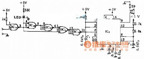
Light and sound sensor circuit diagram
(View)
View full Circuit Diagram | Comments | Reading(2990)
Light Sensor Circuit
Published:2012/9/19 21:24:00 Author:Ecco | Keyword: Light Sensor
This Circuit can compare the Light level in an area. It uses a PN Photodiode as the light sensor and IC CA3140 as voltage comparator. The circuit is ideal as the front end of burglar alarm circuits.The circuit uses an Op Amp as voltage comparator. In voltage comparator mode, the OpAmp compares the voltage levels between its inverting input (pin2) and the non- inverting input(pin3) and gives an appropriate high / low output. Generally in voltage comparator mode, voltage at one input is kept fixed using a Zener diode or a potential divider resistor chain. In the circuit, the voltage at pin 3 is set by VR1 so as to keep the output high in a particular light level. The high output keeps the LED off. The PN Photodiode act as the light sensor. When the light reduces, current through the photodiode decreases. This increases the voltage at pin 2 of comparator and the output swings to low state. Current then flows through R2 and LED into the comparator and LED lights. This indicates, low light level or darkness.
Light Sensor Circuit
?
4 Responses to “Light Sensor Circuit”
Source: electroschematic.com (View)
View full Circuit Diagram | Comments | Reading(2050)
BACK_BIASED_GaAsP_LED_OPERATES_AS_LIGHT_SENSOR
Published:2009/6/30 23:52:00 Author:May
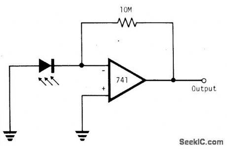
Using a simple 741 amplifier connected as a current-to-voltage converter with the LED as the current source, the voltage at the output is proportional to incident light. The junction is biased only by the difference between the summing node junction potential and ground, preventing the possibility of reverse break-down. The photon-generated current equals the short-circuit current of the junction, which is linearly related to incident light. The sensor requires a level of incident illumination that depends on the degree of opacity of the LED package. (View)
View full Circuit Diagram | Comments | Reading(3201)
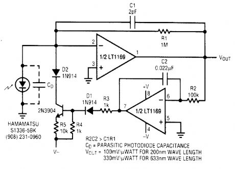
LOU_NOISE_LIGHT_SENSOR_WITH_dc_SERVO
Published:2009/6/22 22:40:00 Author:May
View full Circuit Diagram | Comments | Reading(1517)
Circuit Categories
power supply circuit
Amplifier Circuit
Basic Circuit
LED and Light Circuit
Sensor Circuit
Signal Processing
Electrical Equipment Circuit
Control Circuit
Remote Control Circuit
A/D-D/A Converter Circuit
Audio Circuit
Measuring and Test Circuit
Communication Circuit
Computer-Related Circuit
555 Circuit
Automotive Circuit
Repairing Circuit