
Temperature Sensor
Index 3
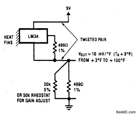
TWO_WIRE_TEMPERATURE_SENSOR_OUTPUT_REFERENCED_TO_GROUND
Published:2009/6/24 4:12:00 Author:May
View full Circuit Diagram | Comments | Reading(1058)
LOW_TEMPERATURE_SENSOR
Published:2009/6/22 23:13:00 Author:May
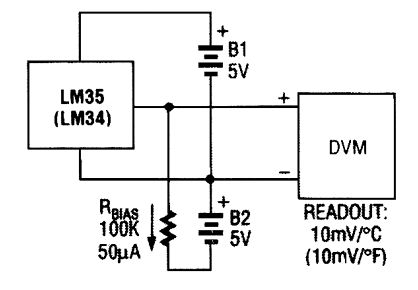
A negative bias current can produce the off-set needed for below-zero readings using the LM34 or LM35 temperature sensor. (View)
View full Circuit Diagram | Comments | Reading(0)
TEMPERATURE_SENSOR
Published:2009/6/22 23:09:00 Author:May
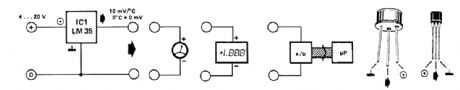
The LM35 temperature sensor provides an output of 10 mV/℃ for every degree Celsius over 0℃. At 20℃ the output voltage is 20 x 10 = 200 mV. The circuit consurnes 60 μA. The load resistance should not be less than 5 kΩ. A 4- to 20-V supply can be used. (View)
View full Circuit Diagram | Comments | Reading(0)
Digital Temperature Meter Circuit
Published:2011/7/17 8:23:00 Author:Robert | Keyword: Digital, Temperature, Meter
The picture shows the digital temperature meter circuit. (View)
View full Circuit Diagram | Comments | Reading(1523)
Temperature-Sensitive Diode Application Circuit
Published:2011/7/10 2:47:00 Author:Robert | Keyword: Temperature-Sensitive Diode, Application
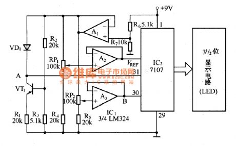
The circuit shown in the picture is the digital temperature meter circuit which uses temperature-sensitive diode as the temperature-measurement element. It is mainly made up of the A/D converter 7107, operational amplifier LM324, 3-digit LED display circuit and temperature-sensitive diode and so on. It features high accuracy, good stability, versatility, ease of use and so on. Its temperature measurement range is 0℃~100℃ with accuracy ±1℃.
The voltage follower, which is made up of the operational amplifier A1, supply power for the A/D converter integrated circuit IC2 and the temperature sampling circuit separately to reduce the interaction between them. The semiconductor transistor VT1 and R1, R2, R3 supply stable bias current for the temperature-sensitive diode VD1. (View)
View full Circuit Diagram | Comments | Reading(2210)
SWF2 Type Temperature Sensor Circuit
Published:2011/6/28 7:17:00 Author:Robert | Keyword: Temperature, Sensor
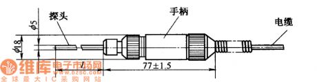
The picture shows the SWF2 type temperature sensor circuit. (View)
View full Circuit Diagram | Comments | Reading(999)
TSV Type Temperature Sennor Typical Application Circuit
Published:2011/5/22 4:04:00 Author:Robert | Keyword: TSV Type, Temperature Sennor, Application
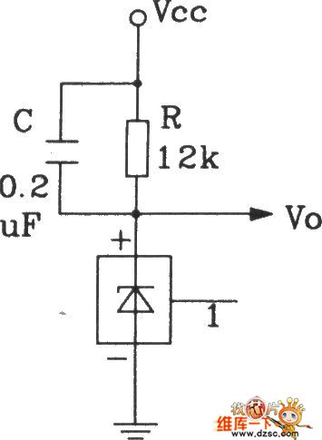
This circuit's output voltage Vo's temeratrue sensitivity is 10mV/°C. The resistance R is current-limit resistance. The capacitor C is used to improve the stability of the circuit. When the test position and the result-reading position have a far distance, the wire resistance's voltage drop would cause some extent measuring errors.
(View)
View full Circuit Diagram | Comments | Reading(812)
Celsius Thermometer Circuit Composed Of LM35DZ Celsius Temperature Sensor
Published:2011/5/17 9:06:00 Author:Robert | Keyword: Celsius, Thermometer, Temperature Sensor
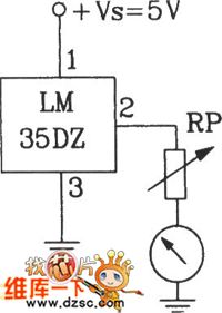
The Celsius Thermometer Circuit Composed Of LM35DZ Celsius Temperature Sensor is shown below.
(View)
View full Circuit Diagram | Comments | Reading(1472)
Precision Celsius Thermometer Circuit Composed Of SL134 Integrated Temperature Sensor
Published:2011/5/17 8:44:00 Author:Robert | Keyword: Precision, Celsius Thermometer, Integrated, Temperature Sensor
The Precision Celsius Thermometer Circuit Composed Of SL134 Integrated Temperature Sensor is shown below.
(View)
View full Circuit Diagram | Comments | Reading(1225)
With Linear Two-Wire RTD Temperature Measuring Circuit (XTR105)
Published:2011/5/12 9:58:00 Author:Robert | Keyword: Linear, Two-Wire RTD, Temperature Measuring
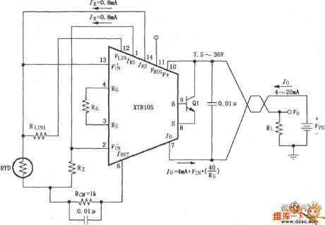
With Linear Two-Wire RTD Temperature Measuring Circuit (XTR105) is show below.
(View)
View full Circuit Diagram | Comments | Reading(1857)
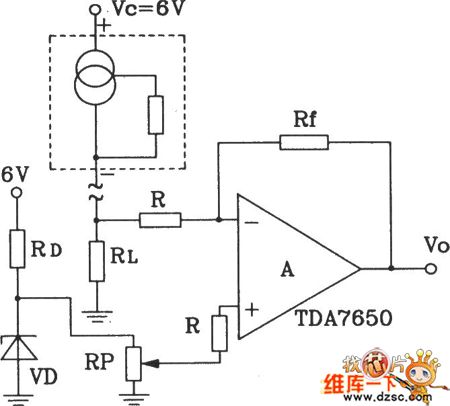
Temperature Sensor of Current Transmission Circuit
Published:2011/5/1 22:30:00 Author:Felicity | Keyword: Temperature Sensor of Current Transmission Circuit,
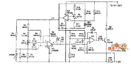
The resistance in the cirtuit is metal film one. Itsaccuracy is better than 1% and temperature coefficient TCis less than ±50X10-6/K.The measuring range is from0℃ to 100℃. Current I= 4+T/6.25. The temperate unit is ℃ and the current unit is mA. The current shows KTY87two-wire current transmitter consisting of Wheatstone bridge with pre-amplifier , current transmitter stage and voltage regulator. (View)
View full Circuit Diagram | Comments | Reading(1019)
XTR101 Thermocouple Input Circuit
Published:2011/4/26 8:05:00 Author:Robert | Keyword: Thermocouple
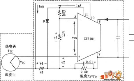
The circuit shows the thermocouple input circuit withtwo temperature zones and diode cold junction compensation. This circuit uses J-type thermocouple as temperature sensor, semiconductor diode Das cold junction temperature compensation to form the relative 0oC of the measurement, to measure the temperature, T1 temperature range is from 0 to 1000oC. The temperature of T2 is equal to the temperature TD of semiconductor diode D. When the measured temperature changes in the range of 0to 1000oC, J-type thermocouple will have a 58mV change. When the ambient temperature is +25oC, the typical value would be 1.28mV. Corresponding 0oC transmission current is 4mA, corresponding 1000oC transmission current is 20mA.
(View)
View full Circuit Diagram | Comments | Reading(1550)
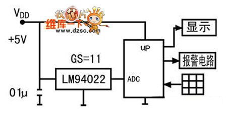
10-bit low-power digital temperature sensor application circuit
Published:2011/3/23 3:04:00 Author:Joan | Keyword: low-power , digital temperature sensor , application circuit
Below is 10-bit low-power digital temperature sensor application circuit.
(View)
View full Circuit Diagram | Comments | Reading(793)
Differential temperature measurement Circuit Diagram
Published:2011/3/21 0:52:00 Author:Joan | Keyword: temperature measurement, Differential temperature
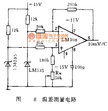
The temperature difference between two points is often measured in many situations. For example, in water pump fan design and other designs, the impeller shape is always detemined by the temperature difference between the entrance and exit. if the difference is small, it requires high precision phase resolution. Figure 8 shows a high sensitivity temperature measurement circuit with 100mV / ℃ sensitivity. The precision op amp LM308 ouput 10 times of the differential temperature voltage the two temperature sensors measured. The Op amp output will be 0 by adjust the Rw when the two sensors are in the same temperature.
(View)
View full Circuit Diagram | Comments | Reading(2839)
-55-+150℃ Digital thermometer circuit diagram
Published:2011/3/30 20:52:00 Author:Ecco | Keyword: -55-+150℃ Digital thermometer
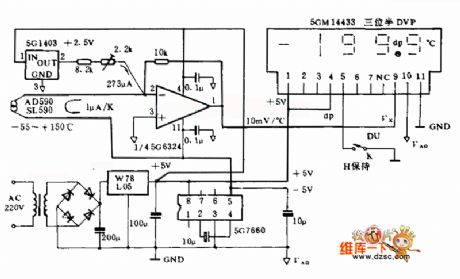
This digital thermometer electrocircuit is composed of SL590, a new semiconductor IC temperature-sensitive sensor and three half digital voltage panel 5GM14433, and it can measure the temperature in the range of -55~15o ℃. The SL590 make the temperature be a type of current semaphore, which become ratio's voltage semaphore at Celsius temperature after making the null point displacement by operational amplifier, and sent to the UX input terminal of 5GM14433, then be digital quantity displayed by LED. The supply is d.c two types, and alternating current supplyed by 220V, also could be supplyed by 4 pieces of 1.5V batteries.
(View)
View full Circuit Diagram | Comments | Reading(3201)
-40-+125℃ digital thermometer circuit diagram
Published:2011/3/30 20:42:00 Author:Ecco | Keyword: digital thermometer
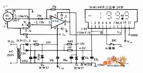
This digital thermometer electrocircuit is composed of SL616, a newsemiconductor IC temperature-sensitive sensor and three half digital voltage panel(DVP)s, and it uses the SL616 A to measure the temperature in the ranges of -40~125 ℃. And it uses the SL161 C to measure the temperature in the ranges of -25~85 ℃, measurement accuracy after correcting is ±0.5 ℃. Its power supply use 3 sets of +6 V, ±the 10, and only +6 V power supply consume higher current(about the 65 mas), each ±10 V power supply the only consume about 3 mA current.
The digital thermometer creates corresponds thermal voltage semaphore(-10 mVs/K), then the semaphor is become ratio's voltage semaphore(+10 mVs/℃) at Celsius temperature after making the null point displacement by operational amplifier, and sent to DVP to carry on digitize display as thermal amount of indication.
(View)
View full Circuit Diagram | Comments | Reading(2395)
Fahrenheit scale circuit diagram
Published:2011/3/20 22:56:00 Author:Ecco | Keyword: Fahrenheit scale
Fahrenheit scale circuit diagram is as below:
(View)
View full Circuit Diagram | Comments | Reading(949)
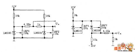
LM135 temperature telemetry circuit
Published:2011/3/21 1:46:00 Author:Joan | Keyword: LM135 , temperature telemetry
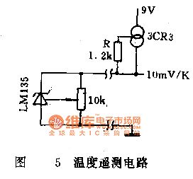
When the measurement point is far away from the display meter, the voltage drop caused by the sensor's operating current in the connection conductor, superimposed on the output voltage on the sensor, will produce some measurement error. To eliminate the effect of the resistance of connecting wires, the circuit can be used as shown in Figure 5. By the use of constant current source driver LMl35, the sensor operating current is constant, and the connection lead resistance is fixed, then the voltage drop across the wire is a certain value, which can be corrected by calibration terminal to ensure the accuracy of measurements.
(View)
View full Circuit Diagram | Comments | Reading(1417)
LM135 package and pin function circuit
Published:2011/3/18 1:53:00 Author:Joan | Keyword: package, pin function
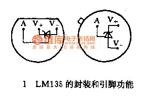
LM135 Series Temperature Sensor is a voltage output type precision integrated temperature sensor. It works similar to the Zener diode, the reverse breakdown voltage changes with the absolute temperature in +10 mV/K ratio. The working current is 0.4 - 5mA, and the dynamic impedance is 1Ω, which facilitate matching to instruments. The temperature sensor features high accuracy and simple application. LMl35 series temperature sensor has wide temperature measurement range of -55 to +150 ℃. LM235 and LM335 temperature measurement ranges of -40 - +125 ℃ and -40 - +100 ℃. The short-term use temperature measurement limit can be widened, respectively, to 200 ℃, 150 ℃ and 125 ℃.
(View)
View full Circuit Diagram | Comments | Reading(1185)
LM135 Series Internal schematic diagram
Published:2011/3/18 1:28:00 Author:Joan | Keyword: Internal schematic diagram
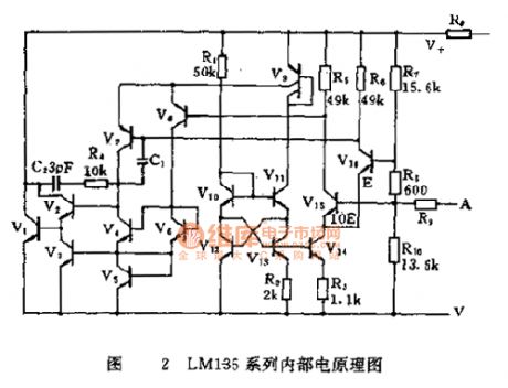
LM135 Series Internal schematic diagram
(View)
View full Circuit Diagram | Comments | Reading(1206)
| Pages:3/4 1234 |
Circuit Categories
power supply circuit
Amplifier Circuit
Basic Circuit
LED and Light Circuit
Sensor Circuit
Signal Processing
Electrical Equipment Circuit
Control Circuit
Remote Control Circuit
A/D-D/A Converter Circuit
Audio Circuit
Measuring and Test Circuit
Communication Circuit
Computer-Related Circuit
555 Circuit
Automotive Circuit
Repairing Circuit