
Temperature Sensor
Index
Make straight play three digital voltmeter circuit diagram
Published:2014/2/18 21:47:00 Author: | Keyword: Make straight play three digital voltmeter circuit diagram,
Make straight play three digital voltmeter circuit diagram
(View)
View full Circuit Diagram | Comments | Reading(1554)
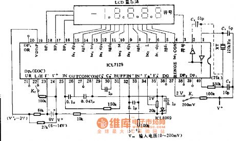
Four and a half LCD digital voltmeter circuit diagram
Published:2014/2/18 21:44:00 Author: | Keyword: Four and a half LCD digital voltmeter circuit diagram,

Four and a half LCD digital voltmeter circuit diagram
(View)
View full Circuit Diagram | Comments | Reading(1861)
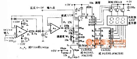
Four and a half LED counting circuit diagram
Published:2014/2/18 21:41:00 Author: | Keyword: Four and a half LED counting circuit diagram,
Four and a half LED counting circuit diagram
(View)
View full Circuit Diagram | Comments | Reading(1485)
Constant Temperature Circuit
Published:2013/3/10 23:05:00 Author:Ecco | Keyword: Constant Temperature

The 7805 voltage regulator provides a reference voltage that is fed into a resistive bridge formed on one side by the 20K trimmer and the other side by the 3.3K resistor and the 1K/thermistor combination. The termistor is an NTC (Negative Temperature Coefficient) type. The op-amp is run in a differential mode and tries to keep its inputs at the same potential by the thermal feedback loop formed by the heater and the thermistor.
The three 1N4001 diodes are used to bias the emitter of the transistor up enough that it can shut off fully with the limited voltage swing from the 741 op-amp. The heating indicator LED (a standard red LED) also taps off of the same diode ladder to enable it to shut off entirely.
The value of the (1uF) capacitor in the op-amp feedback loop may need to be adjusted if the circuit rings , or swings back and forth before stabilizing on a temperature. The capacitor value is specific to the thermal mass that is being temperature stabilized.
The heater resistor is rated at approximately 40 ohms and 5 watts. The value of the resistor determines the heating rate and the power consumption. The resistor value should not be too low or the resulting high current will damage the 1N4001 diodes and/or the TIP122 transistor.
(View)
View full Circuit Diagram | Comments | Reading(1700)
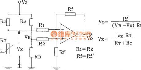
Temperature sensor current transmission circuit
Published:2012/10/11 21:21:00 Author:Ecco | Keyword: Temperature sensor, current transmission
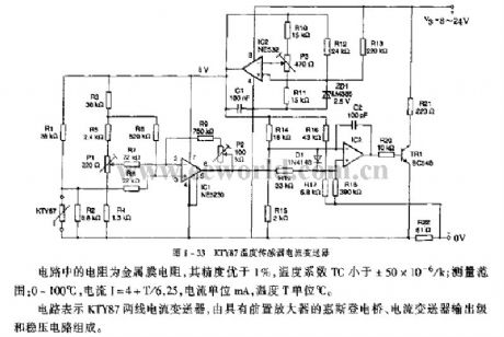
Resistors in the circuit use metal film resistors, and its accuracy is better than 1%, and the temperature coefficient TC is less than ± 50 × 10-6 / k; measuring range: 0 to 100 ° C , the current I = 4 + T/6.25, current unit is mA, and temperature T unit is ℃. The circuit is composed of KTY87 two-wire current transducer, Wheatstone bridge with preamplifier, current transmitter output stage and regulator.
(View)
View full Circuit Diagram | Comments | Reading(2202)
Temperature sensor transmitter circuit
Published:2012/9/11 1:30:00 Author:Ecco | Keyword: Temperature sensor, transmitter
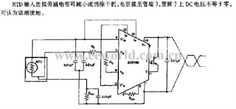
RTD input is connected to bypass capacitor to reduce or eliminate the interference. When the capacitor is connected to pin 7 of pipe, the DC voltage on pin 7 is not equal to zero, that means the pin 7 is grounded.
(View)
View full Circuit Diagram | Comments | Reading(1376)
Temperature sensor interface circuit
Published:2012/9/11 1:23:00 Author:Ecco | Keyword: Temperature sensor, interface
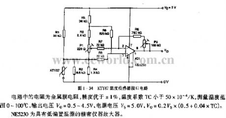
The resistor in circuit uses a metal film resistor, and its precision is better than ± 1 %, temperature coefficient TC is less than 50 × 10-4 / K, measurement temperature range is between 0~ 100 ℃, output voltage Vo = 0.5 ~ 4.5V, supply voltage VS = 5.0 V, Vo = 0.2VS × (0.5 +0.04 × TC). NE5230 is a low bias temperature precision instrument amplifier.
(View)
View full Circuit Diagram | Comments | Reading(1841)
TEMPERATURE SENSOR WITH 4 TO 20mA CURRENT LOOP
Published:2012/9/10 20:24:00 Author:Ecco | Keyword: TEMPERATURE SENSOR , 4 TO 20mA , CURRENT LOOP
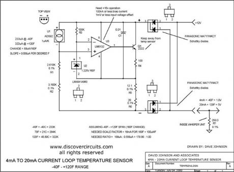
I designed a circuit similar to this one years ago to accurately measure the air temperature inside a building 1000s of feet from a control room. The circuit uses a very robust current loop method. It uses a highly accurate semiconductor temperature sensor and an equally accurate voltage reference. The circuit includes a diode bridge, so it is polarity independent. By using the component values indicated, the circuit should not require calibration. It has a range from ?40F to +120F and an accuracy of +/- one degree F.
Source: discovercircuits (View)
View full Circuit Diagram | Comments | Reading(2388)
LM134-LM10 Thermometer/Temperature Sensor
Published:2012/9/3 3:08:00 Author:Ecco | Keyword: Thermometer, Temperature Sensor
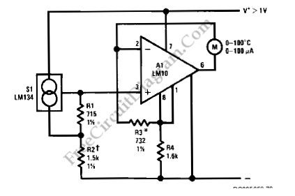
Using LM134 and LM10 integrated circuits, we can build a thermometer which has -55 to 150°C sensing range. The ideal meter for this circuit is a 0-200uA digital ampere meter, which can show both positive and negative polarity. This will make the circuit suitable for indicating temperatures below 0°C. LM134 is basically a current source with very accurate and consistent temperature coefficient, so many temperature sensing application find it suitable for the sensor. Here is the schematic diagram of the circuit: (Source: freecircuitdiagram)
(View)
View full Circuit Diagram | Comments | Reading(2453)
Temperature-voltage transform circuit composed of precision temperature sensor
Published:2011/8/26 3:08:00 Author:Jessie | Keyword: Temperature-voltage transform, temperature sensor
View full Circuit Diagram | Comments | Reading(1516)
Total positive supply long-distance transmission circuit composed of LM35DZ celsius temperature sensor
Published:2011/8/26 2:49:00 Author:Jessie | Keyword: supply long-distance transmission, celsius temperature sensor
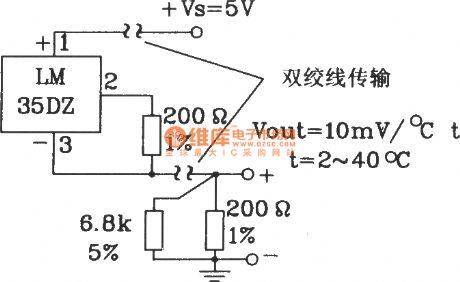
View full Circuit Diagram | Comments | Reading(1283)
In ground for long-distance transmission circuit composed of LM35DZ celsius temperature sensor
Published:2011/8/26 2:49:00 Author:Jessie | Keyword: long-distance transmission, celsius temperature sensor

View full Circuit Diagram | Comments | Reading(1360)
four-and-a half display voltage meter formed by the single-chip CMOS IC circuit
Published:2011/8/11 4:13:00 Author:John | Keyword: four-and-a half display voltage meter, single-chip, CMOS, IC
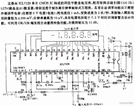
This is the four-and-a half display voltage meter composed of the ICL7129 monolithic CMOS IC. It is equipped with the multi-scan matrix (100Hz) LCD (liquid crystal display) digital device. It is especially for production of high-resolution pocket multimeter. It has the auto-zero function without the need for external capacitors. Only a 9V power supply (battery) is required. The current consumption is only 1mA and the changing speed is 2 times / second. Its direct input analog voltage range is ± 200 mA and its maximum bit resolution is 10μV. When the power supply voltage is lower than7.2V, the alarm and display functions can be identified. (View)
View full Circuit Diagram | Comments | Reading(2600)
CMOS four-and-a half decimal counter circuit
Published:2011/8/11 3:54:00 Author:John | Keyword: CMOS four-and-a half decimal counter
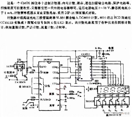
This is the CMOS four-and-a half decimal counter, which includes the count, the latch, by-bit scanning output circuit and protection circuit inside. Only an external capacitor is needed to change the scanning speed freely. Its power supply voltage is within 3 ~ 10V and its static current consumption is less than 1mA. The counting frequency ranges from dc to several megahertz. And it uses DIP-16 pin package.
The counting pulses are coupled to DG6010 from high-speed photodiode isolator SL950 to count. Then the BCD code sent by DG6010 is converted into 7-segment signal by CC4511B. Then the 7-segment signal is added to four-phase LED to display.
(View)
View full Circuit Diagram | Comments | Reading(1696)
MARK_SENSOR_FOR_CARDS
Published:2009/7/20 10:23:00 Author:Jessie
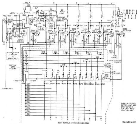
Automatically transcribes up to 40 pencil marks on specially printed 90-column cards into machine code and block-punches information into cards in any desired format at 150 cards per minute -F. A. Frankl, Transcribing Field Markings by Optical Scanning, Electronics, 34:31, p 49-51. (View)
View full Circuit Diagram | Comments | Reading(0)
Smart Temperature Sensor MAX6698 With 7 Channels Circuit
Published:2011/7/28 6:38:00 Author:Robert | Keyword: Smart, Temperature, Sensor, 7, Channels
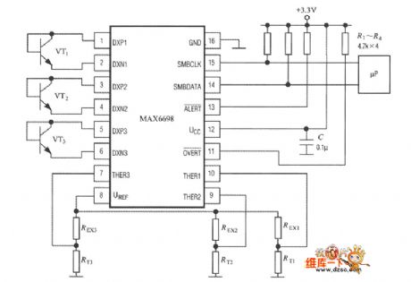
As shown, the MAX6698 could only fully connect three temperature-measuring transistors (VT1~VT3) and three thermistors (RT1~RT3). Its internal referenced voltage source UREF would supply for the three thermistors through the resistance REX1~REX3 separately. The voltage-drop would be send to pin of THER1~THER3 separately. The temperature-measuring transistor could select the CMPT3904, SST3904, KST3904-TF, SMBT3904, FMMT3904CT-ND and other types. (View)
View full Circuit Diagram | Comments | Reading(1264)
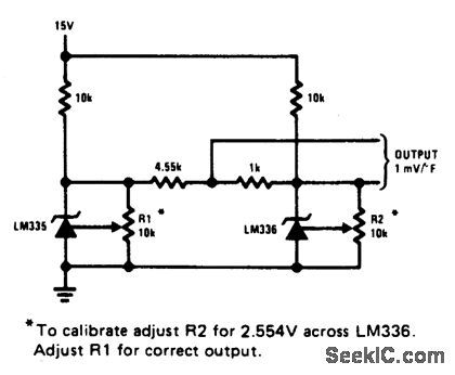
FAHRENHEIT_THERMOMETER
Published:2009/6/29 2:03:00 Author:May
View full Circuit Diagram | Comments | Reading(1096)
BASIC_DIGITAL_THERMOMETER_CELSIUS_AND_FAHRENHEIT_SCALES
Published:2009/6/29 2:02:00 Author:May
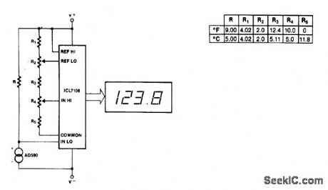
Maximum reading on the Celsius range is 199.9 ℃, limited by the (short-term) maximum allowable sensor temperature. Maximum reading on the Fahrenheit range is 199.9 °F (93.3 ℃), limited by the number of display digits. VREF for both scales is 500 mV. (View)
View full Circuit Diagram | Comments | Reading(1352)
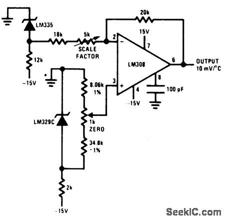
GROUND_REFERRED_CENTIGRADE_THERMOMETER_1
Published:2009/6/29 1:59:00 Author:May
View full Circuit Diagram | Comments | Reading(1912)
TEMPERATURE_SENSOR_1
Published:2009/6/29 1:58:00 Author:May
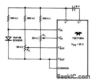
View full Circuit Diagram | Comments | Reading(1018)
| Pages:1/4 1234 |
Circuit Categories
power supply circuit
Amplifier Circuit
Basic Circuit
LED and Light Circuit
Sensor Circuit
Signal Processing
Electrical Equipment Circuit
Control Circuit
Remote Control Circuit
A/D-D/A Converter Circuit
Audio Circuit
Measuring and Test Circuit
Communication Circuit
Computer-Related Circuit
555 Circuit
Automotive Circuit
Repairing Circuit