
Detection Signal Generating
Index
Infrared Beam Break Detector
Published:2013/8/13 4:06:00 Author:lynne | Keyword: Infrared Beam Break Detector

The IR sensor responds to pulsed infrared, not ambient or continuous IR. This means that another transmitter project is necessary in order to complete this one! Note though that some forms of lighting like fluorescent lighting may interfere with the sensor. For convenience, the the buzzer is internally driven so that a only Vdc is needed to make a sound. In this case, the IR sensor senses 38kHz pulsed infrared light.
Pin 3 of the IR sensor is actually low (0V) while receiving a signal. When the sensor is blocked from receiving the IR signal, the sensor outputs a high signal to the comparator, which then allows current through the LED/Buzzer circuit, and alerting you that the beam is broken. In the Scheme-It drawing the LM311 IC is a grouping of three components, in a functional block diagram style, to show how it functions in the circuit beyond what the pinouts would show normally.
(View)
View full Circuit Diagram | Comments | Reading(1050)
LOW_BATTERY_DETECTOR
Published:2009/7/9 20:55:00 Author:May
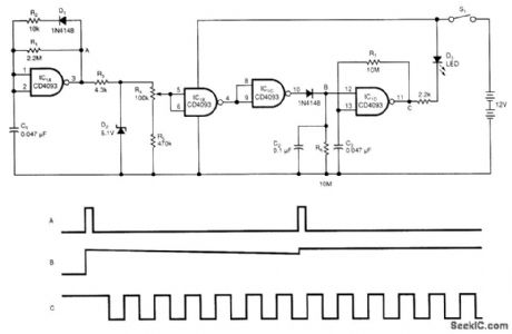
The battery low-voltage detector uses a CD4093 Schmitt trigger and a capacitor that acts as a 1-bit dynamic RAM. The circuit conserves power by using a periodic test method. IC1A, C1, R1, R2, and D1 generate a narrow, positive pulse at point A.
D2, R4, and R5 regulate and divide the signal at A. Thus, the input of IC1B is independent of the power supply. Because the threshold voltage of the Schmitt trigger depends on the power supply, the threshold voltage will drop if the power-supply voltage drops. When the threshold voltage is lower than the input voltage, IC1B will become low, and IC1C's output will become high.
Capacitor C2 stores the results of the periodic test. The time constant C2 and R6 set is 1 s, and the test period is approximately 0.1 s. When point B is high, which implies that the battery is low, IC1D, C3, and R7 generate a square waveform, which lights D3. You can adjust the detected voltage level by adjusting R4. You can test different battery voltages by changing the voltage level of D2. (View)
View full Circuit Diagram | Comments | Reading(0)
Multi-Function Infrared Control Counter Circuit
Published:2011/4/24 6:35:00 Author:Robert | Keyword: Multi-Function, Infrared, Counter
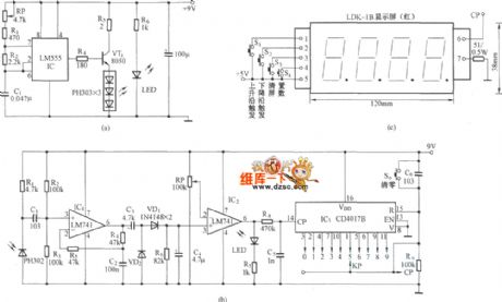
Multi-Function Infrared Control Counter Circuit is shown below:
(View)
View full Circuit Diagram | Comments | Reading(1143)
Circuit Categories
power supply circuit
Amplifier Circuit
Basic Circuit
LED and Light Circuit
Sensor Circuit
Signal Processing
Electrical Equipment Circuit
Control Circuit
Remote Control Circuit
A/D-D/A Converter Circuit
Audio Circuit
Measuring and Test Circuit
Communication Circuit
Computer-Related Circuit
555 Circuit
Automotive Circuit
Repairing Circuit