
High Frequency Signal Generating
Index
Integrated Circuit of High-fidelity Dual Track Amplifier TDA2616
Published:2011/9/12 23:57:00 Author:Zoey | Keyword: Integrated Circuit, High-fidelity, Dual Track, Amplifier
1.Circuit Diagram and pin function of TDA2611A
TDA2616 is used as power amplifiers in TV sounders, compound sounders and active sounders.
There are two identical audio frequency amplified circuits in TDA2616 integrated block. Its integrated block interior circuit and dual power supply circuit have been presented in the picture. In this IC, pin 9 is single inline encapsulation, pin function and statistics have been presented in the chart.
2 Main parameters of TDA2616
(1) Dual power supply. If Vcc=±16V, R(l)=8Ω,THD=0.5%,Po=12W. If THD=10%,Po=15W.
(2)Single power supply. If Vcc=24V, THD=10%, if R(l)=4Ω, Po=14W.
3 Typically-applied Circuit of TDA 2616. As shown in picture, they refer to TDA dual power supply circuit and integrated block single power supply circuit respectively.
4 Malfunction Examination and repair alert
Whether it is a single supply or dual power supply, when there is a silent failure, we should firstfigure ourifthe squelch circuit isin the wrong starting state. We canjudge the statebycutting off pin 2.
(View)
View full Circuit Diagram | Comments | Reading(1122)
the relaxation oscillation circuit with 300MHZ frequency modulation
Published:2011/9/8 6:16:00 Author:Ariel Wang | Keyword: relaxation oscillation , 300MHZ, frequency modulation
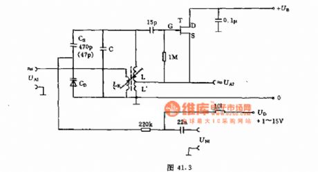
The oscillation circuit signals come from UA2 or UA1.LK is one turn within 300MHZ.L' is about 10% of L's turns.You can do frequency fine adjustment to UD using varactor CD.And you can do frequency modulation to UNF.If you want to choose the capacitor CS,you can refer to the frequency range and the varactor based on the frequency offset required.The capacitor C in oscillating circuit can be chosen as the way above.
(View)
View full Circuit Diagram | Comments | Reading(997)
56 ~ 484 khz high frequency oscillator
Published:2011/7/29 1:56:00 Author:Ecco | Keyword: 56 ~ 484 khz high frequency oscillator
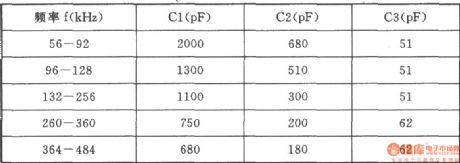
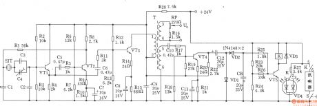
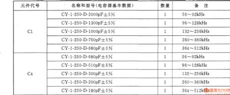
High frequency oscillator is shown as the figure, it can be used as special high-frequency generator, selecting different capacitance between 56 ~ 484 kHz can generate a high frequency. The circuit has the advantages of good shave waveform, high stability of frequency, low output impedance. Selection of components: transistor VTl, VT2: 3DG6D, 65 ≤ β 115, VT3, VT4: 3DGl308, 60 ≤ β ≤ 85. Semi-adjustable capacitor C4: CCWX-3-5/20pF. Crystal SJT: BE-42 type. K: JZX-10M (mini relay). Light-emitting diode VD4: BT-605 (red, green color). Variable device T: using MXD-2000 ferrite, GV-30 × 19 core. Ll-2Φ0.21mm high-strength wire with 133-turn winding, L3-4Φ0.21mm high-strength wire with 11 turns, L5-6Φ0.21mm high-strength wire with 80 turns. Nominal power of resistor uses l/2WRJ models and R27, the other type of resistor are 1/8WRJ. Other parameters of marked element are shown as the chart, there’s no special requirement. The relationship between frequency and capacitor values are shown as below.
(View)
View full Circuit Diagram | Comments | Reading(934)
Impedance matching circuit diagram of high-frequency circuit test
Published:2011/7/16 9:38:00 Author:Sophia | Keyword: High-frequency circuit test, Impedance matching
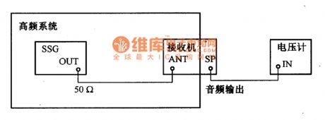
When High-frequency circuit is tested, its impedance match of cable, testers are very important.Impedance usually is 5OΩ or 75Ω. The diagram is the basic connection type to measure the receiver sensitivity. The impedance of the receiver usually is 50Ω, so the output impedance of standard signal generator(SSG) also should be 5OΩ. We should notice the following points: the connecting impedance of the measuring equipment should be identical; the impedance of electric cable should be identical; connector should have excellent impedance chracteristic within the limits of measuring frequency; the cable should be as short as possible; high-powered tester should be adopted; the output terminal of SSG should connect high-frequency fuse wire. (View)
View full Circuit Diagram | Comments | Reading(628)
Frequency characteristic of shunt capacitance circuit diagram
Published:2011/7/16 9:39:00 Author:Sophia | Keyword: Shunt capacitance, Frequency characteristic

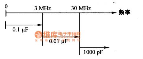
Power supply decoupling circuit usually adopts shunt capacitance and choose the optimum capacity and variety according to the frequency band of the circuits. Especially in high frequency circuit, shunt capacitance can reduce the power supply impedance, so the choice of the capacitor should choose deliberately. The diagram is the impedance and frequency chacateristic of ceramic capacitor. Theoretically, the capacitor impedance is 1/(2πfC). But the higher capacitance, the higher frequency, the lower impedance. because of the influence of the internal impedance, in excess of regular frequency, the impedance of the real capacitor will be higher on the contrary. So when the impedance reach the lowest point, the capacitance will be low and the frequency will be the highest. In the diagram a and b, when the capacitance is 10000pF, the frequency is 10MHZ; when the capacitance is 1000pF, the frequency is 40MHZ. When the frequency is high, shunt capacitance adopts low capacity capacitance, which will have better effect than high capacity.
(View)
View full Circuit Diagram | Comments | Reading(693)
down-lead of high frequency circuit
Published:2011/6/27 9:30:00 Author:chopper | Keyword: down-lead, high frequency circuit
In the high frequency circuit,the inductance and capacitance of the down-lead effect circuit a lot and the supply lead is very important.We should reduce the impedance of landlines as possible as we can in the high frequency range.As for high frequency circuit, it includes landlines basically besides element lines and signal lines.Thus,all parts of the groud of the circuit can be connected by any routes and the impedance among the groud is very low.The picture a,b are printed plate wiring examples of single pipe broadband amplifier circuit.We can know there are all landlines besides down-leads.
(View)
View full Circuit Diagram | Comments | Reading(587)
The relationship circuit diagram betweent frequency band and capacitance capacity
Published:2011/6/9 22:38:00 Author:Sophia | Keyword: Frequency band, Capacitance capacity
The diagram shows that the capacitance should be adopted with different capacitance, the capacitor should adopt ceramic capacitor with excellent frequency characteristic.
(View)
View full Circuit Diagram | Comments | Reading(607)
56 ~ 512kHz high frequency oscillator
Published:2011/4/20 22:05:00 Author:Ecco | Keyword: 56 ~ 512kHz , high frequency , oscillator
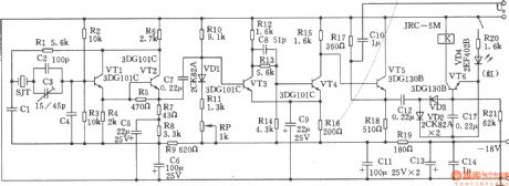
The chart shows the 56 ~ 512kHz high frequency oscillator. It consists of high-frequency oscillator, the alarm circuit. 1. Specifications: (1) Frequency range: 56 ~ 512 kHz; (2) Output Level: +5.5 ± ldB; (3) Frequency Accuracy: less than ± 20Hz; (4) warning signal: when stopping vibration, the warning light turns on and the circuit emits alarm sound. (5) Operating temperature: 0 ~ +45 ℃ assurance indicators, -10 ~ 0 ℃, +45 ~ +50 ℃; reliable working components’ choice: Transistor VTl ~ VT4: 3DGl01C, β = 65 ~ 85, VT5 ~ VT6: 3DGl308 , β = 85 ~ 115. Crystal SJT: the model is 101 quartz crystal, crystal with t feet that is GZC7-F. The choices of capacitors Cl and C4 are according to the attached table.
(View)
View full Circuit Diagram | Comments | Reading(1619)
Voltage-regulator tube high-frequency signal generator
Published:2011/4/25 4:33:00 Author:Ecco | Keyword: Voltage-regulator tube , high-frequency , signal generator

Using the breakdown characteristics of zener regulator can get the high frequency signal which can be up to several hundred MHz, the circuit is shown as the chart. The signal removing from the output end V01 is a single frequency signal, which can be used to fine-tune the resonant frequency of tuned circuit. The signal removing from the output end V02 is the broad spectrum of high-frequency signal, which can enter the tune the system between the input resonant circuit and the oscillator tuning circuit in superheterodyne radio circuit. Generator frequency range is l00kHz ~ 27MHz, which is divided into five bands of 100kHz ~ 300kHz ~ l MHz ~ 3MHz ~ 9MHz ~ 27MHz. Signal generator's output voltage is 9mV. Ll ~ L5 coil is rounded with skeleton, with fine-tuning core. Ll ~ L3 are enameled with Φ0.1mm wires, L4, L5 are enameled with Φ0.2mm wires. The number of turns of Ll ~ L5 is 270 +270, 260, 80, 30 and 10. After assembly, it needs to be corrected by the standard calibration signal generator, and mark the frequency scale on the knob of the variable capacitor C3. Adjusting Potentiometer make the output frequency signal be strongest. Regulator used in the circuit is without special requirements, but the value of the supply voltage should be higher than the regulator to ensure the regulator operating in the inflection point on the curve.
(View)
View full Circuit Diagram | Comments | Reading(803)
Simple high-frequency signal generator
Published:2011/4/20 6:51:00 Author:Ecco | Keyword: Simple , high-frequency , signal generator
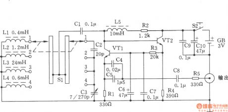
The chart shows a simple high-frequency signal generator. Changing the inductance of LC resonant circuit by the band switch Sl will change the frequency range of high frequency oscillation. This machine can be divided into four stages: the first stage is in 0.4 ~ 2MHz; the second stage is in 2 ~ 10MHz; the third stage is in 9 ~ 45MNz; fourth stage is in 60 ~ 110MHz. Components Selection: VTl, VT2 use the NPN silicon tube with fT ≥ 800MHz, β ≥ 100 of, such as 9018, C535 and so on. All resistors use 1/8W carbon film resistors. Capacitor C5 uses a monolithic capacitor or other ceramic capacitor. L2, L3, L4, L5 use high-frequency magnetic inductors and they can also be self-wound. Ll uses Φ0.6mm high strength wire with 8 flat close turns, and it is wound as the coil with inner diameter in Φ7mm . Sl uses the two-pole four roll band switch.
(View)
View full Circuit Diagram | Comments | Reading(2449)
Circuit Categories
power supply circuit
Amplifier Circuit
Basic Circuit
LED and Light Circuit
Sensor Circuit
Signal Processing
Electrical Equipment Circuit
Control Circuit
Remote Control Circuit
A/D-D/A Converter Circuit
Audio Circuit
Measuring and Test Circuit
Communication Circuit
Computer-Related Circuit
555 Circuit
Automotive Circuit
Repairing Circuit