
Intermediate Frequency Signal Generating
Index
A8800 IF signal processing integrated circuit diagram
Published:2011/4/28 1:26:00 Author:Ecco | Keyword: IF, signal processing , integrated circuit
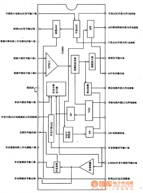
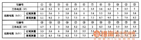
TA8800 is an IF signal processing integrated circuit produced by Toshiba, it is widely used in domestic and imported large screen color TV. 1. The features of functionTA8800 IC embedded video zoom, video detector, high frequency and IF AGC, VIF amplification, intermediate frequency amplification and sound processing circuit. 2. Pin functions and dataTA8800 integrated circuit block diagram and the pin functions are shown in Figure 1, the operating parameters are listed in Table 1. Figure 1 is the block diagram and pin functions of TA8800 integrated circuit. Table 1 shows operating parameters of TA8800 integrated circuit.
(View)
View full Circuit Diagram | Comments | Reading(597)
Intermediate frequency signal generator made by 3L465 ceramic filter
Published:2011/4/24 22:32:00 Author:Ecco | Keyword: Intermediate frequency , signal generator, ceramic filter
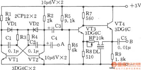
Figure shows the intermediate frequency signal generator made by 3L465 ceramic filter, the line is simple, easy to start up, the resulting IF signal is stable, it has a good repeatability and outputs audio signal. Working principle: VTl, VT2 and related components form a multivibrator with frequency in 400Hz, it is used to modulate IF signal, audio signal can be output from the A point. VT3, VT4 form an IF signal generator, DL has the selected frequency effect. RP can change the oscillation intensity adjustment. Leading a wire of a few centimeters in B point to output modulated IF signal. Multivibrator can work when getting power if welding is correct. The inspection part of the IF signal generator circuit is correct, it can use a medium-radio to close to the B point leading wire, adjusting the RP make the radio receive the signal, then the adjustment is end. When using, the radio wave band switch should be put at medium wave, the variable capacitor is adjusted to the the low-spin, and then point B closing to the AM ferrite antenna coil lead wire, and then one by one repeatedly adjusting the frequency transformer make the speaker's voice or added to voltage be the maximum.
(View)
View full Circuit Diagram | Comments | Reading(1292)
Circuit Categories
power supply circuit
Amplifier Circuit
Basic Circuit
LED and Light Circuit
Sensor Circuit
Signal Processing
Electrical Equipment Circuit
Control Circuit
Remote Control Circuit
A/D-D/A Converter Circuit
Audio Circuit
Measuring and Test Circuit
Communication Circuit
Computer-Related Circuit
555 Circuit
Automotive Circuit
Repairing Circuit