Sine Signal Generating
Stable sine wave oscillator composed of F007
Published:2011/4/21 6:39:00 Author:Ecco | Keyword: Stable sine wave oscillator | From:SeekIC
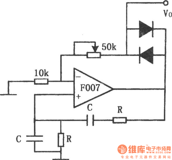
The chart shows the stable sine wave oscillator circuit. In order to obtain a stable oscillation, it requires a loop gain with 1. If the gain is too large, the waveform will occur distortion; if the gain is too small, the circuit will stop vibration. This circuit uses two diodes to stabilize the oscillation. When the output voltage is too low, the diode cuts off, negative feedback is cut off, the loop gain to improve the output voltage increased. When the output reaches a certain value, the diode conduction, the loop gain is improved, output voltage increases. And when the output rate reaches a certain value. The potentiometer in the figure is used to adjust the output amplitude and distortion. The oscillation frequency of the circuit is decided by the resistor R and capacitor C: f0 = 1/2πRC.
Reprinted Url Of This Article:
http://www.seekic.com/circuit_diagram/Signal_Processing/Sine_Signal_Generating/Stable_sine_wave_oscillator_composed_of_F007.html
Print this Page | Comments | Reading(3)

Article Categories
power supply circuit
Amplifier Circuit
Basic Circuit
LED and Light Circuit
Sensor Circuit
Signal Processing
Electrical Equipment Circuit
Control Circuit
Remote Control Circuit
A/D-D/A Converter Circuit
Audio Circuit
Measuring and Test Circuit
Communication Circuit
Computer-Related Circuit
555 Circuit
Automotive Circuit
Repairing Circuit
Code: