
Sine Signal Generating
Index
Simple sinusoidal oscillator circuit
Published:2011/10/27 21:13:00 Author:May | Keyword: sinusoidal oscillator
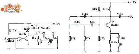
It can change the frequency range, and the oscillating signal is adjusted by potentiometer RP1. Since the output resistance is very low ( 1KΩ),it issuitable for various kinds of control circuit as a source.
In the circuit, the transistor's collector passesthrough R1, R2, C1, C2 to base to constitute feedback branch. Changing the device's parameters is OK.
(View)
View full Circuit Diagram | Comments | Reading(2095)
Sine wave generation schematic circuit diagram
Published:2011/9/9 1:57:00 Author:Ecco | Keyword: Sine wave generation
View full Circuit Diagram | Comments | Reading(2345)
HYPERBOLIC_SINE
Published:2009/7/6 23:27:00 Author:May
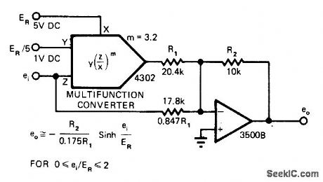
Burr-Brown 4302 multifunction converter and opamp generate hyperbolic sine transfer function with response matching ideal curve within 0.7%. Technique permits setting powers and roots at fractional as well as integer values. Converter shown is set for exponent of 3.2. Choice of amplifier gain and ref erence voltage scales response for given input and output signal levels. Article gives design equations.-J. Graeme, Sinh Generator Boasts 0.7% Error, END Magazine, Aug. 5, 1978, p 70 and 72. (View)
View full Circuit Diagram | Comments | Reading(1000)
20_20000Hz_SINE_SQUARE
Published:2009/7/6 4:35:00 Author:May
Opamp is used as tuned circuit driven by square wave from yoltage comparator Frequeny is controlled by R1-R3, C1, and C2, with R3 providing tuning.Comparator is fed with resulting sine wave to obtain square wave for feedback to input of tuned circuit, to cause oscillation. Zener stabifizes amplitude of square wave that is fed back.R6 and C5 provide DC negative feedback around comρarator to ensure starting.Values of C1 and C2 are equal,and range from 0.4 μF for 18-80Hz to 0.002 μF for 4.4-20 kHz.-''Easily Tuned Sine Wave Oscillator,″National Semiconducotor,Santa Clara,CA,1971,LB-16. (View)
View full Circuit Diagram | Comments | Reading(1088)
SINE_COSINE
Published:2009/7/6 3:58:00 Author:May
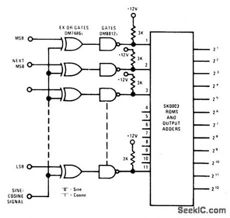
Uses National SK0003 sine/cosine look-up table kit consisting of four MOS ROMs and three output adders. Combination implements equation sin θ=sin M cos L + cos M sin L.Worst-case error is 1 5/8 bits in least significant bit. Cosine is approximated with loss in resolution of1/2 bit in 11-bit input or1/4 bit in 10-bit input.- Memory Databook, National Semiconductor, Santa Clara, CA, 1977, p 6-98-6-99. (View)
View full Circuit Diagram | Comments | Reading(997)
10_kHz_SINE_COSlNE
Published:2009/7/6 0:52:00 Author:May
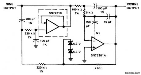
Combination of SN72310 voltage-follower opamp and SN 72301A high-performance opamp gives two outputs differing in phase by 900. Supply is ±18 V.- The Linear and Interface Circuits Data Book for Design Engineers, Texas Instruments, Dallas, TX, 1973, p 4-40. (View)
View full Circuit Diagram | Comments | Reading(733)
WIEN_SINE_WAVE
Published:2009/7/5 23:53:00 Author:May
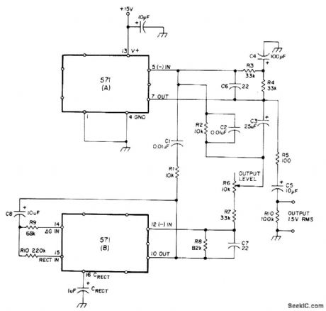
Uses NE571 analog compandor in oscillator circuit based on Wien network formed by R1-C1 and R2-C2, placed around output amplifier of section A to make it bandpass amplifier. Section B serves as inverting amplifier with nominal gain of 2. Total harmonic distortion is below 0.1%. Operating frequency is about 1.6 kHz for values shown, but can be varied from 10 Hz to 10 kHz. Frequency is l/21πRCforR = R1 = R2 and C = Cl = C2. R should be kept between 10K and 1 megohm and C between 1000 pF and 1 μF. Useful as fixed-frequency oscillator but can be tuned if matched dual pot is used for R1.R2.-W. G. Jung, Gain Control IC for Audio Signal Processing. Ham Radio, July 1977, p 47-S3. (View)
View full Circuit Diagram | Comments | Reading(1411)
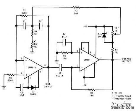
350_Hz_STABILIZED_SINE_WAVE
Published:2009/7/5 22:20:00 Author:May
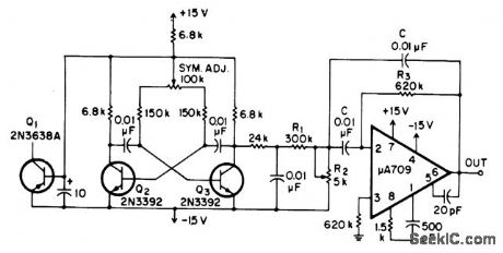
Squarewave oscillator Q2-Q3 stabilized by Q1, followed by passive filter and active filter using μA709, produces amplitude-stabilized sine wave at 350 Hz, for which third harmonic is 39 dB down and other harmonics are insignificant.-E. Neugroschel and A. Paterson, Amplitude-Stabilized Audio Oscillator, EEE Magazine, April 1971, p 65. (View)
View full Circuit Diagram | Comments | Reading(659)
25_Hz_SINE_WAVE
Published:2009/7/5 22:14:00 Author:May
Output voltage is 8 V P-P at about 25 Hz for values shown, with total harmonic distortion less than 0.5%. Circuit will operate from 15 Hz to 100 kHz by using other values. Set regeneration control Rl, at minimum value needed to sustain oscillation.-J. C. Freebom, Simple Sinewave Oscillator, EDN/EEE Magazine, Sept. 1, 1971, p44. (View)
View full Circuit Diagram | Comments | Reading(862)
STABILIZED_SINE_WAVE
Published:2009/7/5 21:09:00 Author:May
Peak detector is used with FET operated in voltage variable.-resistance mode. in combination with standard double-integration circuit having regenerative feedback. to give 1.46-kHz sinewave output into 500-ohm load at 10 V P-P. Will operate at power supply voltages off 8 to 18 V whhout appreciable variation in output amplitude or frequency. Output varies less than 1.5% in frequency and 6% in amplitude over temperature range of 10 to 65°c. Circuit can be modified for other frequencies.-F. Macli. FET Stabilizes Sine-Wave Oscillator. EDN Magazine. June 5.1973. p 87. (View)
View full Circuit Diagram | Comments | Reading(797)
234_kHz_SINE_WAVE
Published:2009/7/5 20:56:00 Author:May
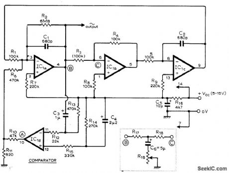
Uses low-cost LM3900N quad differential amplifier IC in lowdistortion oscillator for which third harmonic distortion is typically 0.5%. Peak-to-peak amplitude of sine-wave output is typically 25% of source voltage VCC. Frequency can be changed by altering single component. R3. or by inserting between points B and C an RC network and pot connected as shown in inset. Article gives design equations for frequency and Q.-T. J. Rossiter. Sine Oscillator Uses C.D.A. Wireless World. April 1975. p 176. (View)
View full Circuit Diagram | Comments | Reading(1168)
100_kHz_SINE
Published:2009/7/2 1:06:00 Author:May
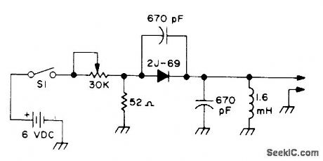
Tunnel-diode sine-wave oscillator uses single GE 2J-69. Frequency is stable provided there are no drastic temperature changes, but for long-term accuracy and stability a crystal oscillator is recommended.-Circuits, 73 Magazine, May 1977, p 31. (View)
View full Circuit Diagram | Comments | Reading(1126)
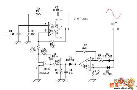
The sine wave oscillator circuit with adjustable frequency, constant amplitude composed of F007
Published:2011/7/29 2:09:00 Author:Ecco | Keyword: sine wave oscillator , adjustable frequency, constant amplitude

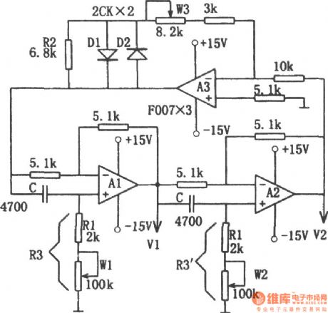
Figure shows the sine wave oscillator circuit with adjustable frequency, constant amplitude. The circuit consists of two sub-phase circuit and a linear concatenation of the inverting amplifier. Phase-shifting circuit is the combination of integrated operational amplifier A1, A2 and the RC. Since the phase shift of inverter A3 is 180o, therefore, two phase circuits should also be phase-shifted 180o to ensure that the requirements of the circuit oscillation condition with the total phase shift in 360o.The dynamic resistance of diodes D1, D2 is very high when the voltage being low, so the high-gain inverting circuit ensures the start-up circuit. When the oscillation amplitude rises, the dynamic resistance of D1, D2 getting smaller and smaller reduce the gain of the circuit, so that the output amplitude is stable. Because the diode has a larger dead zone voltage, small signal output waveform has stopped, it is added a resistor R2. The oscillation frequency of the circuit:
Adjusting potentiometer W1 and W2 can change the frequency. As the phase shift circuit has no effect on amplitude, the regulation frequency does not affect the stability of amplitude. W1 can adjust the frequency changing in about 10 times, the scope of its regulatory role is not obvious when over the range, then it can be adjusted by w2.
(View)
View full Circuit Diagram | Comments | Reading(2379)
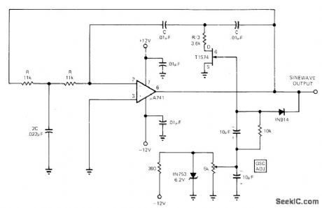
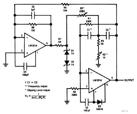
Sine wave signal source with stable output
Published:2011/7/28 3:24:00 Author:Ecco | Keyword: Sine wave , signal source , stable output

Figure shows the sine wave signal source with stable output. First using of an op amp comparator could produce a constant 60Hz square wave. The output end of comparator is connecting to a pair of 6.2V back connecting zener diodes. The following is a two-stage Sallen-key low pass filter, which canfilter out all harmonics. Capacitive coupling amplifier cuts off the DC component produced by zener diode which is not equal in circuit, it also make compensation for filter loss, and the precise calibration of the output amplitude can reach l0V peak. The result is that it gets a high stable 60Hz sine wave voltage with low distortion. In the case of constant ambient temperature, power supply voltage range is 90 ~ 135V, the sine wave output voltage rate of change is less than 5mV.
(View)
View full Circuit Diagram | Comments | Reading(933)
Digital sine wave generator
Published:2011/7/28 3:23:00 Author:Ecco | Keyword: Digital , sine wave, generator
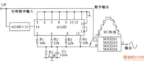
Digital sine wave generator is shown as the chart. It consists of analog digital converter (4018B) and a fixed filter (MAX29X). One part of the clock pulse input CP drives MAX29X filter, and the others makes fractional frequency by the first 10-bit counter (4018B) and then by the second l0-bit counter. The output step wave becomes smooth sine wave by R5 and Cl, and then it is output after filtered by the filter. The output frequency changes with the input of clock, the relationship is fout = fin/l00.
(View)
View full Circuit Diagram | Comments | Reading(0)
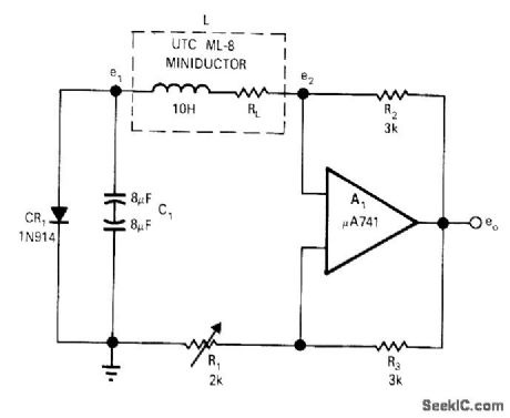
Simple sine wave generator composed of μA741
Published:2011/7/29 2:12:00 Author:Ecco | Keyword: Simple, sine wave , generator

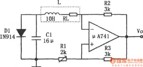
The chart shows a simple sine wave generator circuit. The circuit can produce the sine wave with less distortion, the oscillation frequency:
According to the data presented in this chart, the oscillation frequency is about 25Hz. Changing the value of inductor L and capacitor C can change the oscillation frequency from 15Hz to 100kHz, the total harmonic distortion can be less than 0.5%, while the upper frequency limit is controlled by the operational amplifier. The potentiometer R1 can adjust the amount of positive feedback added to series resonant circuit. Oscillation condition is that resistor R1 should be equal to the inductance sum of DC resistor RL and inductor. Diode D1 is used to limit the signal voltage to prevent saturation of inductor and operational amplifier. In order to get the distortion as small as possible, the value of resistor R1 should be as low as possible, it but must be able to ensure the maintenance of oscillation.
(View)
View full Circuit Diagram | Comments | Reading(3297)
LOW_DISTORTION_SINE_WAVE_OSCILLATOR
Published:2009/6/22 23:46:00 Author:May
C1,C2Min.Frequency Max.Frequency0.47μF 18 Hz 80 Hz 0.1μF 80 Hz 380 Hz 0.022μF 380 Hz 1.7 kHz0.0047μF 1.7 kHz 8 kHz0.002μF 4.4 kHz 20 kHz (View)
View full Circuit Diagram | Comments | Reading(0)
PURE_SINE_WAVE_GENERATOR
Published:2009/6/18 21:55:00 Author:May
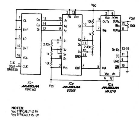
A TTL counter, an 8-channel analog multiplexer, and a fourth-order low-pass filter can generate 10- to 25-kHz sine waves with a THD better than -80 dB. The circuit cascades the two second-order, continuous-time Sallen-Key filters within IC3 to implement the fourth-order low-pass filter.To operate the circuit, choose the filter's cutoff frequency,fC, by tying IC3's D0 through D6 inputs to 5 V or ground. The cutoff frequency can be at 128 possible levels between 1 and 25 kHz, depending on those seven digital input levels. Because the circuit ties D0 through D6 to ground, fC equals 1 kHz. The 100-kΩ potentiometer adjusts the output level between VDD - 1.5 V and VSS + 1.5 V. (View)
View full Circuit Diagram | Comments | Reading(5)
SINE_WAVE_SHAPER
Published:2009/6/18 21:51:00 Author:May
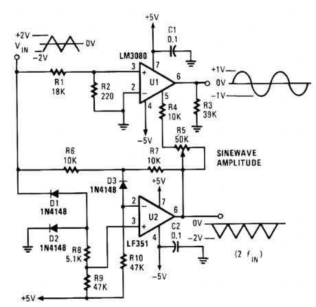
Unlike most sine-wave shapers, this circuit is temperature stable. It varies the gain of a transcon-ductance amplifier to transform an input triangle wave into a good sine-wave approximation. (View)
View full Circuit Diagram | Comments | Reading(3)
SINE_WAVE_GENERATOR
Published:2009/6/18 21:50:00 Author:May
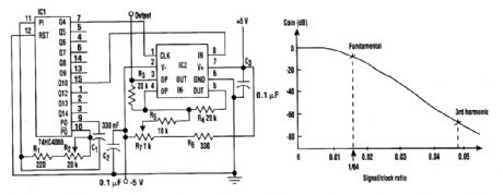
In this circuit, a square wave is filtered by a high-order low-pass filter so that a -3-dB frequency will eliminate most harmonics of the waveform. As a result, the filter outputs a fundamental sine wave. This method is applied to generate a sine wave by using a switched-capacitor filter (MAX292) (see the figure). This circuit offers wide frequency range (0.1 Hz to 25 kHz), low distortion, and con-stant output amplitude throughout the whole frequency range. (View)
View full Circuit Diagram | Comments | Reading(155)
| Pages:1/2 12 |
Circuit Categories
power supply circuit
Amplifier Circuit
Basic Circuit
LED and Light Circuit
Sensor Circuit
Signal Processing
Electrical Equipment Circuit
Control Circuit
Remote Control Circuit
A/D-D/A Converter Circuit
Audio Circuit
Measuring and Test Circuit
Communication Circuit
Computer-Related Circuit
555 Circuit
Automotive Circuit
Repairing Circuit