Sine Signal Generating
The sine wave oscillator circuit with adjustable frequency, constant amplitude composed of F007
Published:2011/7/29 2:09:00 Author:Ecco | Keyword: sine wave oscillator , adjustable frequency, constant amplitude | From:SeekIC

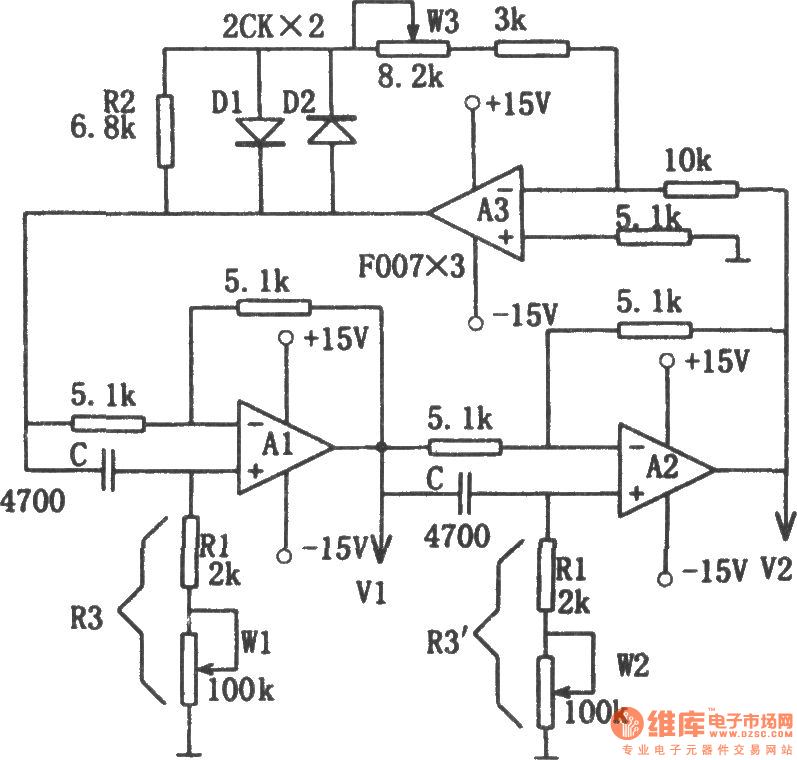
Figure shows the sine wave oscillator circuit with adjustable frequency, constant amplitude. The circuit consists of two sub-phase circuit and a linear concatenation of the inverting amplifier. Phase-shifting circuit is the combination of integrated operational amplifier A1, A2 and the RC. Since the phase shift of inverter A3 is 180o, therefore, two phase circuits should also be phase-shifted 180o to ensure that the requirements of the circuit oscillation condition with the total phase shift in 360o.The dynamic resistance of diodes D1, D2 is very high when the voltage being low, so the high-gain inverting circuit ensures the start-up circuit. When the oscillation amplitude rises, the dynamic resistance of D1, D2 getting smaller and smaller reduce the gain of the circuit, so that the output amplitude is stable. Because the diode has a larger dead zone voltage, small signal output waveform has stopped, it is added a resistor R2. The oscillation frequency of the circuit:
Adjusting potentiometer W1 and W2 can change the frequency. As the phase shift circuit has no effect on amplitude, the regulation frequency does not affect the stability of amplitude. W1 can adjust the frequency changing in about 10 times, the scope of its regulatory role is not obvious when over the range, then it can be adjusted by w2.
Reprinted Url Of This Article:
http://www.seekic.com/circuit_diagram/Signal_Processing/Sine_Signal_Generating/The_sine_wave_oscillator_circuit_with_adjustable_frequency_constant_amplitude_composed_of_F007.html
Print this Page | Comments | Reading(3)

Article Categories
power supply circuit
Amplifier Circuit
Basic Circuit
LED and Light Circuit
Sensor Circuit
Signal Processing
Electrical Equipment Circuit
Control Circuit
Remote Control Circuit
A/D-D/A Converter Circuit
Audio Circuit
Measuring and Test Circuit
Communication Circuit
Computer-Related Circuit
555 Circuit
Automotive Circuit
Repairing Circuit
Code: