
Index 116
Average temperature measurement circuit composed of AD590(accurate integrated temperature sensor with current output)
Published:2011/9/10 22:03:00 Author:Felicity | Keyword: Average temperature measurement circuit, current output, accurate integrated temperature sensor
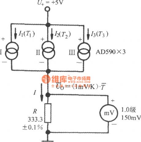


The figure shows the average temperature measurement circuit composed of AD590.The current through R is:.and the indication of the 1.0 millvoltmeter is the average temperature:i.e.Generally, assumed that the number test point is n and then the average temperature is:
(View)
View full Circuit Diagram | Comments | Reading(1446)
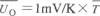
Current-fed Push-pull Inverting Circuit
Published:2011/8/25 22:53:00 Author:Michel | Keyword: Inverting Circuit
Current-fed push-pull inverter circuit is shown as picture 1 and the DC voltage is sent to center tap when it flows through the inductance L.L1 and the capacitance C2 which is cross overed between Tr primary winding constitute formalities resonance circuit and R1 ,R2 and R3 constitute start-up circuit.The principle circuit is the same as figure 2, because of the Np and Nb positive feedback effect, drive VT1 and VT2 condcut in turns.In this circuit, switch the transistor's collector bears highest voltage is as π times as DC voltage,VDC.
For the countries,United States, Japan and Taiwan whose utility voltage is 110 V / 120 V / 127 V ,this circuit is suitable. (View)
View full Circuit Diagram | Comments | Reading(3402)
ISPl362 and USB Host Interface Circuit
Published:2011/8/25 22:51:00 Author:Michel | Keyword: Host Interface Circuit

CC1020 signal sending and receiving interface and micro-controller connects are shown as the picture 1.Micro controller uses pins P2.6 , bidirectional synchronous data interface DIO, DCLK connection of P3.4 ,CC1020.
The two-way pins of micro-controller isconnected withCC1020 DIO.And it is used to emit and receive data (input and output). DCLK must be connected to an input terminalofthe micro-controller when it provides data.
Data output can choose to use separate pins. At this time to the register ,SEP_DI_DO=1 of CC1020 INTERFACE needs beset up.In synchronous mode, LOCK pins are used for data output,DCLK pins are used for asynchronous mode data output and DIO pins are used for the data input.
The micro-controller a pins can be used as the locking signal of locked phase loop,namely,LOCK pins signal.When phase locked loop is locked, LOCK pins is logic low PWL. It can also be used as a carrier detection and other internal test signal. (View)
View full Circuit Diagram | Comments | Reading(1816)
Delay Pulse Generating Circuit of SN7490
Published:2011/8/25 22:38:00 Author:Michel | Keyword: Delay Pulse, Generating Circuit
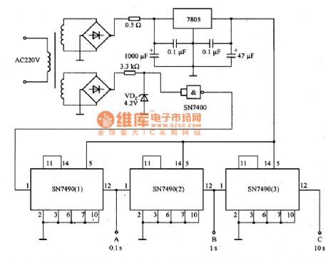
Picture 1 is delay pulse generating circuit of SN7490.They use 220V,50Hz AC as benchmark delay pulse generating circuit. In the circuit,A port can output 0.1s,B terminal outputs 1s and C end can output 10s time delay pulse.It can be used as benchmark pulse circuit and it is the basic form of digital counter the circuit.
Picture 1:Delay Pulse Generating Circuit of SN7490
(View)
View full Circuit Diagram | Comments | Reading(2233)
SAA7121 Digital Video Coding Integrated Circuit
Published:2011/8/25 22:47:00 Author:Michel | Keyword: Digital Video, Coding Integrated Circuit
SAA7121 is digital video coding integrated circuit produced by Philips.It is widely used in VCD and DVD players.
First,Functions Features
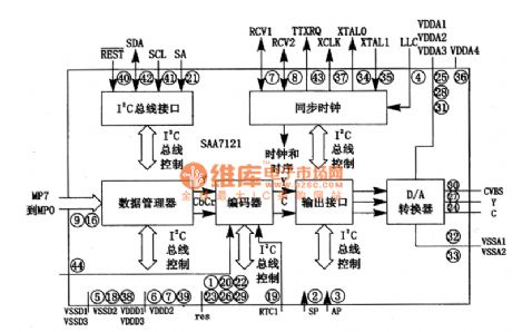
SAA7121 integrated circuit supports NTSC and PAL-M B/G ~ TV pattern.It uses lzC control means and receives decompressed video data via the 8 bits of data bus.The built-in encoder codes digital brightness signal and chromaticity signal into the simulation CVSB and S video signal.It is composed of the data management unit, encoders, output interface, lObitD/A converter, synchronous clock circuit and the I2C bus interface and other components.Its inside circuit block diagram of intergrated block is shown as picture 1.
Picture 1:Inisde Circuit Block Diagram of SAA7121 Intergrated Block
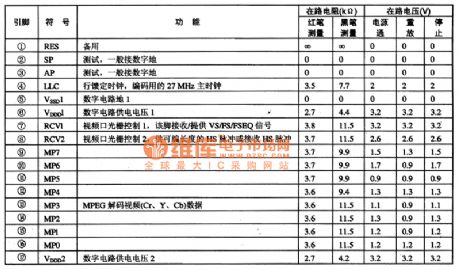
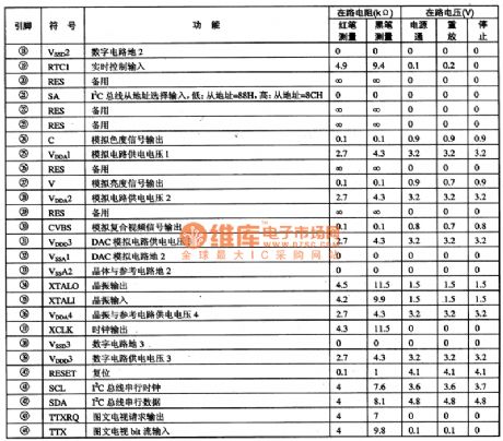
Second,Pins Functions and Data
SAA7121 adopts 44 feet package and its pins functions and data are shown as picture 1. (View)
View full Circuit Diagram | Comments | Reading(1242)
Frequency Synthesizer Integrated Circuit of S14133T
Published:2011/8/25 22:46:00 Author:Michel | Keyword: Frequency Synthesizer, Integrated Circuit
S14133T is frequency synthesizer integrated circuit and it is widely used in cellphones,such as TCL18 cellphones etc.
First,Functions Features S14133T integrated circuit contains first and second vibration,phase lock loop circuit, frequency synthesizer, clock and data circuit.
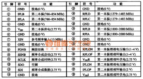
Second,Pins Functions and DataS14133T integrated circuit uses 28 feet and 4 columns flat type encapsulation,which is same as the S14133一MLP28 of Samsung A200 and A288 mobile phones but they could not exchange with each other.S14133T IC pins functions and data are shown as table 1.
Table 1:S14133T IC Pins Functions (View)
View full Circuit Diagram | Comments | Reading(1090)
PCA8516 Characters Form Integrated Circuit
Published:2011/8/25 22:43:00 Author:Michel | Keyword: Characters Form, Integrated Circuit
PCA8516 is character type integrated circuit that is produced by Philips Company and it is widely used in the big screen color TV,for example,ChangHong DT2O00 times frequency color TV.
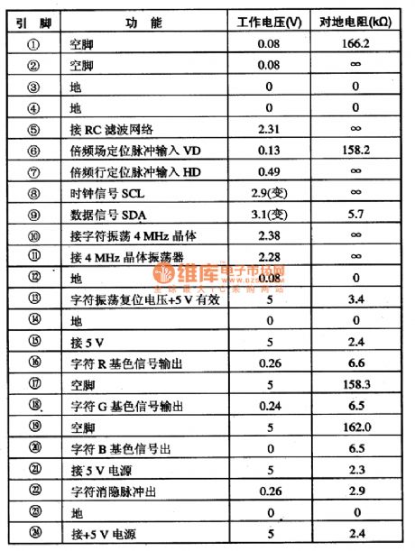
PCA8516 integrated circuit contains the field line positioning pulse processing circuit, characters and clock oscillating circuit, characters and gezer signal circuit, character display vanishing circuit and some other auxiliary functions circuit. The IC adopts 24 DIP package and its pins functions and data are shown as table 1.
Table 1:PCA8516 Pins Functions and Data (View)
View full Circuit Diagram | Comments | Reading(704)
Impulse Current Prevention Circuit of Thyristor
Published:2011/8/25 22:41:00 Author:Michel | Keyword: Thyristor, Impulse Current, Prevention Circuit
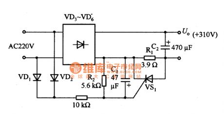
This is impulse current prevention circuit of thyristor as above.When AC power supply is connected, the power switch may be burnt and smooth communication power supply circuit flows through larger impact current.In the circuit,thyristor VS1 makes the current prevent resistance from shortcircuit.The repeating/broken thyristor can work reliably and there is no necessary to worry about the contact's life problem. The delay time is determined by resistance R2 and capacitance C1.
If diodes VD3 ~ VD6 and smooth capacitance C2 are ignored ,impact current will be IP≤UP/R1=35.9A.Current limiting resistor R1 value is larger,the impulse current peak is smaller and but charging time of smooth capacitance grows longer. (View)
View full Circuit Diagram | Comments | Reading(835)
74 series digital circuit of 74LS398/399 4-bit 2-to-1 data selector
Published:2011/8/11 3:20:00 Author:Lucas | Keyword: 74 series , digital circuit, 4-bit , 2-to-1 data selector
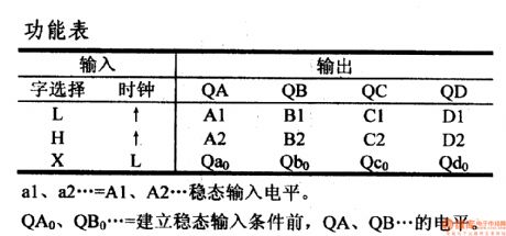
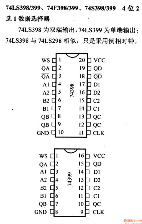
a1, a2 ...= A1, A2 ... steady input level. QA0, QB0 ...= QA, QB ... level before the establishment of steady-state input conditions.74LS398/ 74LS399, 74F398/ 74LS399, 74S398/ 74LS399 4-bit 2-to-1 data selector 74LS398 has dual-ended output, and 74LS399 has single-ended output; 74LS398 and 74LS298 are similar, and they use the reverse phase clock.
(View)
View full Circuit Diagram | Comments | Reading(1164)
74 Series digital circuit of 74293,74LS293 4-bit binary counter
Published:2011/8/12 2:22:00 Author:Lucas | Keyword: 74 Series , digital circuit, 4-bit binary counter
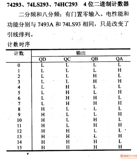
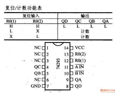
Ithas zero gate input. Electrical performance and functionality are the same with the 7493A and 74LS93. It just changes the lead arrangement.
(View)
View full Circuit Diagram | Comments | Reading(4272)
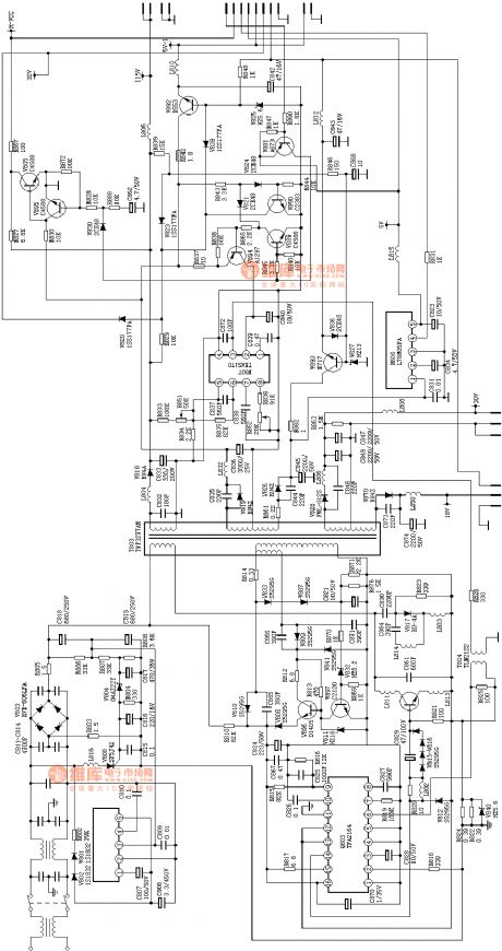
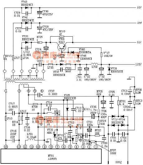
the absolutely useful switch power supply :the C7428 power supply(A4)
Published:2011/8/20 2:20:00 Author: | Keyword: absolutely useful, switch power supply
View full Circuit Diagram | Comments | Reading(951)
the power supply of A3(A4)
Published:2011/8/20 2:20:00 Author: | Keyword: power supply
View full Circuit Diagram | Comments | Reading(911)
The Power Frequency Noise Filter Circuit (μPC822)
Published:2011/9/6 4:44:00 Author:Felicity | Keyword: Power Frequency Noise Filter
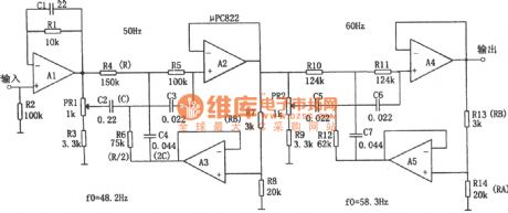
The circuit is a double-T filter to filter out the mixed 50Hz (or 60Hz) power frequency noise when amplifying (such as sensor )weak signal.If only using the RC components to comprise similar filter, usually the value of Q is low and has the attenuation performance of the bandwidth performance .Adopting operational amplifier and positive feedback can increase the value of Q. Supposing that the values of Q is Q', then Q'=Q/(1一K),and K=RA/(RA+RB).Tuning the coefficient Q can increase the value of Q.And the resonant frequency of the circuit is fo=1/2πRC and the positive feedback components are R/2 and 2C. (View)
View full Circuit Diagram | Comments | Reading(2060)
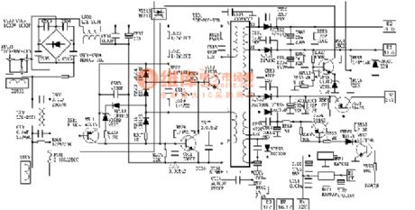
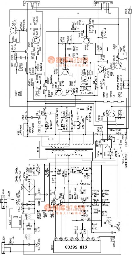
the absolutely useful switch power supply:the SONY KV2185 power supply(A4)
Published:2011/8/20 2:22:00 Author: | Keyword: absolutely useful , switch power supply
View full Circuit Diagram | Comments | Reading(842)
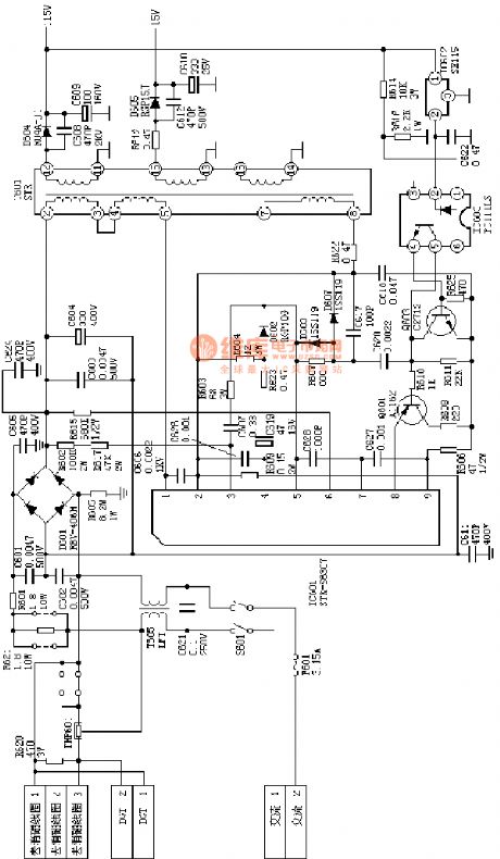
the absolutely useful switch power supply:the SONY KV2184 power supply(A4)
Published:2011/8/20 2:21:00 Author: | Keyword: absolutely useful, switch power supply
View full Circuit Diagram | Comments | Reading(1113)
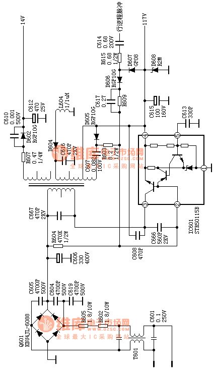
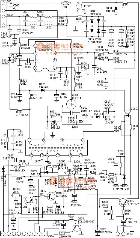
the absolutely useful switch power supply:the sony F29 power supply(A4)
Published:2011/8/20 2:21:00 Author: | Keyword: absolutely useful , switch power supply

View full Circuit Diagram | Comments | Reading(789)
the absolutely useful switch power supply:the Ix0689 power supply(A4)
Published:2011/8/20 2:21:00 Author: | Keyword: absolutely useful , switch power supply
View full Circuit Diagram | Comments | Reading(897)
the absolutely useful switch power supply :the D2902 power supply(A4)
Published:2011/8/20 2:21:00 Author: | Keyword: absolutely useful, switch power supply
View full Circuit Diagram | Comments | Reading(810)
the absolutely useful switch power supply :the C7458 power supply(A4)
Published:2011/8/20 2:21:00 Author: | Keyword: absolutely useful , switch power supply
View full Circuit Diagram | Comments | Reading(858)
Circuit For Driving A Three-wire Fan (Smart Remote Thermal Fan Controller ADT7460)
Published:2011/9/6 4:45:00 Author:Felicity | Keyword: Driving A Three-wire Fan, Smart Remote, Thermal Fan, Controller
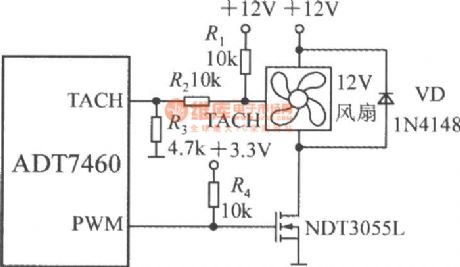
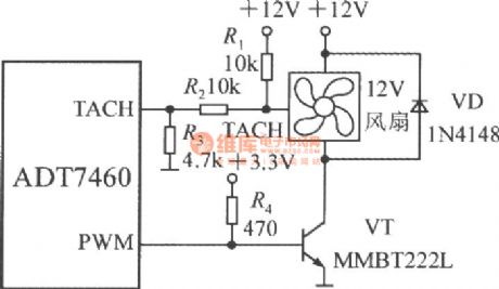
Driven by FET
(View)
View full Circuit Diagram | Comments | Reading(967)
| Pages:116/471 At 20101102103104105106107108109110111112113114115116117118119120Under 20 |
Circuit Categories
power supply circuit
Amplifier Circuit
Basic Circuit
LED and Light Circuit
Sensor Circuit
Signal Processing
Electrical Equipment Circuit
Control Circuit
Remote Control Circuit
A/D-D/A Converter Circuit
Audio Circuit
Measuring and Test Circuit
Communication Circuit
Computer-Related Circuit
555 Circuit
Automotive Circuit
Repairing Circuit