
Index 206
Loom Controller
Published:2011/7/7 2:32:00 Author:Felicity | Keyword: Loom Controller
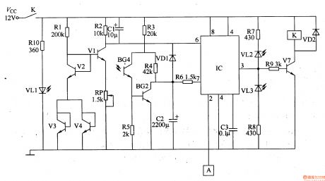
Work of the circuit The circuit consists of touch control circuit, the light control circuit, overheat protection circuit, working status indication circuit and control implementation circuit. (It is showed in picture 8-132.) Touch control circuit consists of touching electrodes A and the circuit inside 2 feet of time-base integrated circuit IC. The light control circuit consists of infrared emitting diode VLl, infrared phototransistor, V5, transistor V6, resistors RlO and R3-R6 and circuit within IC’s pin 7. Overheat protection circuit consists of transistor Vl-V4, diode VD1, resistors Rl and R2, capacitor Cl and C2, potentiometer RP and circuit within IC’s pin 6. Working status indication circuit consists of resistors R7, R8 and LED VLl, VL2. Control implementation circuit consists of transistor V7, relay K, resistor R9 and diode VD2. (View)
View full Circuit Diagram | Comments | Reading(982)
Temperature PID Control Circuit of Operational Amplifier
Published:2011/6/22 6:41:00 Author:Michel | Keyword: Operational Amplifier, Temperature, PID Control Circuit
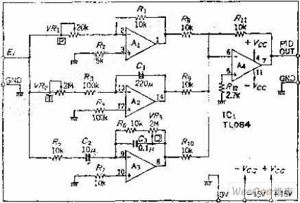
Error integral circuit can be added to the ordinary proportional control circuit if the temperature is controlled and it reaches specified value in the shortest time.But the error will increases as time goes on,the differentiating element is added to the circuit to reduce the error and increase speed and it make quick response to rapid changing temperature and the control is called PID contorl.This circuit form has high accuracy control and it is widely used.
Circuit's Work PrincipleP represents proporation circuit and it's relevant to loop gain.The variable resistance VR1 can change between 0.5~∞ by using the opposite phase the amplifier gain A.
(View)
View full Circuit Diagram | Comments | Reading(6446)
wireless proportion motor remote controller circuit
Published:2011/7/9 10:09:00 Author:Lena | Keyword: wireless, proportion, motor, remote controller
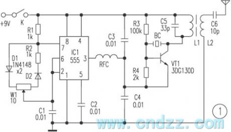
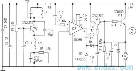
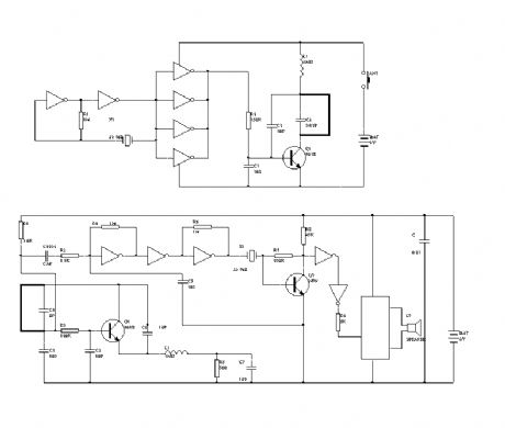
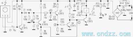
The tri-proportion remote control device is widely used in vehicle model, aeromodelling region etc, which can realize the autocontrol of target drone, model ship and toys. Here introduces a tri-proportion remote controller, the component is purchased easily. The controller has the simple principle and stable performance etc features, which is suited to make unprofessionally.Work principle Figure 1 shows a remote control transmitting circuit, 555 integrated block and R1, R2, W1,D1,D2 and C1 form astable wide range variable dutycycle oscillator, parameter oscillator frequency shown in the figure is about 50Hz.
(View)
View full Circuit Diagram | Comments | Reading(3216)
cordless phone as remote controller circuit
Published:2011/7/9 9:23:00 Author:Lena | Keyword: cordless phone, remote controller
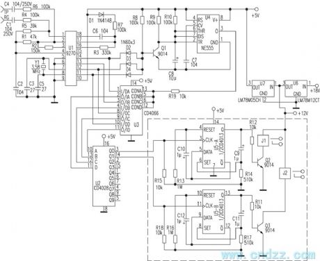
Assembling cordless phone seater and control circuit introduced in the text can obtain the remote control receiver function. Using cordless phone mobile phone as a remote controller transmitter, we can control electric light, electric fan and TV set etc household appliance work.This controller circuit is shown as the figure, TP and RG end connect phone exterior line, namely the circuit is merged with seater. To prevent bringing error when we dial phone, the circuit specially designs the access code using key number as control signal. U1(9270) is DTMF decode integrated circuit.
(View)
View full Circuit Diagram | Comments | Reading(2137)
satellite receiver remote control AC on/off circuit
Published:2011/7/9 10:08:00 Author:Lena | Keyword: satellite receiver, remote control, AC, on/off
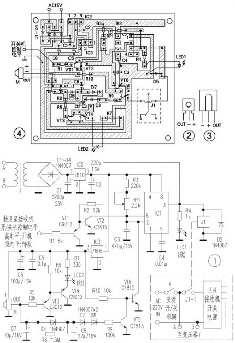
Here introduces a satellite receiver remote control AC on/off circuit, it can be fixed in the receiver, and use former remote controller to realize remote control delay AC on/off function. This circuit has simple structure, easily purchased component, simple manufacture, specially suited for unprofessional electron fans to make.Work principle: The circuit is shown as figure 1. Commercial power is stepped-down by transformer T, and be commuted by rectifier diodes D1-D4, and be regulated by voltage regulator block 7810, 7805, and be filtered by capacitance C1, C2, C5, C6, then it supplies power for the entire circuit.
(View)
View full Circuit Diagram | Comments | Reading(1621)
10-way infrared sequence remote control circuit
Published:2011/7/9 10:02:00 Author:Lena | Keyword: 10-way, infrared, sequence, remote control
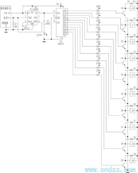
Here introduces a kind of infrared remote control emitter using common household appliance to control 10-way sequence remote control and display circuit. Remote control emitter can adopt usual color TV, video tape recorder , air-condition etc kinds of infrared remote control emitters. So in the manufacture process, we only need product infrared receptor circuit. Infrared receptor circuit mainly consists of integrated infrared receptor apex, NE555 and CD4017 etc integrated circuit, the remote control distance can reach about 15 meters.The circuit is shown in the figure.
(View)
View full Circuit Diagram | Comments | Reading(770)
realizable far distance remote control simple circuit
Published:2011/7/9 9:59:00 Author:Lena | Keyword: realizable, far distance, remote control, simple

The principle and production process of this circuit are as follows:
Infrared receptor apex REM can select currency integration infrared receptor apex, the shape is shown in the figure 1, the infrared remote control signal received by REM is amplified by V1, V2, and the signal drives infrared transmitting tube work. Except for broken line part of figure 1, the other is put in the living room, infrared emitter diode connects coaxial line and receiving part, then be put front shadow of bedroom satellite receptor.
When you possess of this device, you can select TV program that you want conveniently in living room.
(View)
View full Circuit Diagram | Comments | Reading(573)
practicality electromotion curtain remote control circuit 1
Published:2011/7/9 9:57:00 Author:Lena | Keyword: practicality, electromotion curtain, remote control
The transmitting/receiving part of this device uses T966/T988 multiway wireless transceiver module. The transmitting part adopts T966 2-key type emitter, and the receiving part work principle is shown in the figure.
Turn on the power supply, IC2 is restored, Q1 and Q2 output low level, T1 and T2 cut-off, J1 and J2 are not absorbed, motor M stops, the curtain jibs. When press remote control transmitting key C, C end of IC0 outputs high level, D1 cuts-off, I0 end outputs high level, then the high level shape is changed through IC1-1, IC1-2 and is sent to CP1 end of IC2-1.
(View)
View full Circuit Diagram | Comments | Reading(926)
sound surface wave resonator application circuit in the wireless remote control
Published:2011/7/9 9:43:00 Author:Lena | Keyword: sound surface wave, resonator, application circuit, wireless remote control
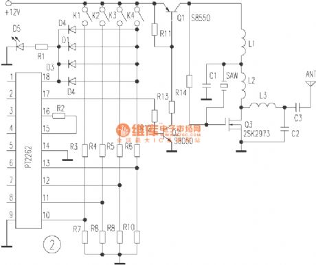
R11-R13, Q1 and Q2 form electron switch modulation circuit, when encoder outputs high level, Q1 conducts, and oscillator emitter electrode works. When encoder outputs low level, Q1 stops to complete ASK modulation. R14, Q3, C1, L1, L2 and sound surface resonator SAW constitutes 315MHZ power master oscillator, Q3 is a high frequency field effect transistor, which can output 1.5W power at 450MHz.
(View)
View full Circuit Diagram | Comments | Reading(1030)
ASK/FM 433/315MHz Emitter Circuit Diagram
Published:2011/7/10 6:05:00 Author:Vicky | Keyword: ASK/FM 433/315MHz Emitter
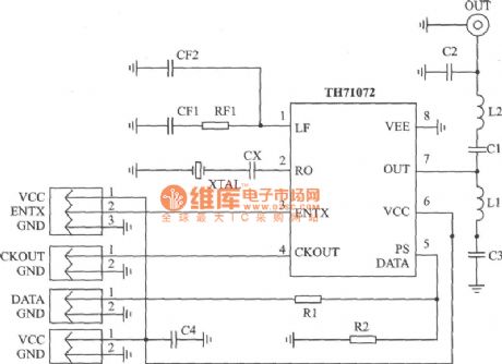
TH71072 applied circuit
TH71072 is a monolithic emitter chip which reaches standards of EN 300 220 and the analogs. It is available for keyless entering system, remote control/remote measuring system, data communication sysytem and security sysetem etc.
Main technical features are as follows:
·Work frequency range: 310~440 MHz;
·ASK modulation mode;
·ASK is conducted by interior power amplifier/gained by closing keying
·FM which makes use ofvariode which is connected externally
·Voltage of power supply: 2.2~5.5 V;
·Work current: 4.8~11.5 mA;
·Output power: -151~-1 dBm. (View)
View full Circuit Diagram | Comments | Reading(936)
ASK 320~290MHz Emitter Circuit Diagram
Published:2011/7/7 8:26:00 Author:Vicky | Keyword: ASK 320~290MHz Emitter
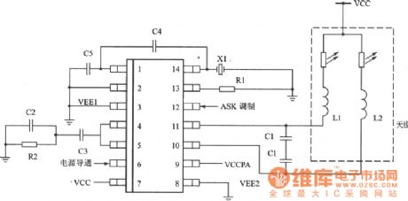
KESTX02 is a monolithic ASK emitter chip which meets therequirment of the basic power of FCC part l5 and harmonic suppression and is suitable for application of underpower wireless.
Main technical features are listed as follows:
·Operating frequency: 290~320 MHz;
·Complete integration of VC0, PLL and power amplifier;
·Low dissipation of current and improve of battery usage duration;
·Voltage of power supply: 3.5~6.5 V;
·Regulation of output power;
·Maximum work current: l2 mA, low power mode current: 0.7μA;
·Cheap exterior fittings.
Applied circuit of KESTX02
(View)
View full Circuit Diagram | Comments | Reading(771)
wireless remote control doorbell circuit
Published:2011/7/9 9:42:00 Author:Lena | Keyword: wireless, remote control, doorbell
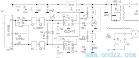
In the figure, these A、B inverter of hex inverter 406 and crystal X1 form a 32.768kHz signal generator, then inverters C, D, E, F are in parallel to modulate high frequency signal generator which is with Q1 as the core, then the generator outputs high frequency modulated wave, Q1 etc elements in figure 2 form a super regeneration receiving circuit, the circuit receives high frequency signal sent from emitter and modulates it to a 32.768kHz signal. The signal is amplified and shaped through C4, R3 and inverter A, B, C, then is filtered via crystal X1, Q2 trigger ding-dong music film to send out doorbell “ding-hu”.
(View)
View full Circuit Diagram | Comments | Reading(2594)
wireless remote control electric fan speed governor
Published:2011/7/9 8:58:00 Author:Lena | Keyword: wireless, remote control, electric fan, speed governor
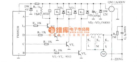
The speed regulating of desk-top electric fan usually adopts musical instrument keys mutual-lock switch controlling inductor spindle head on or off to realize. If we adopt remote control circuit, controlling relay and changing inductance spindle head access or alteration can obtain the same function as the musical instrument keys, and control speed regulating remotely. The remote control transmitting circuit of this electric fan speed governor adopts finished product component TWH9236, which is not shown in the figure. Remote control receiving circuit uses TWH 9238, and data output end A is idle.
(View)
View full Circuit Diagram | Comments | Reading(1416)
BA8207K(Fan) infrared remote control receiving control circuit
Published:2011/6/13 22:05:00 Author:Lena | Keyword: infrared, remote control, receiving
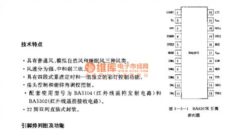
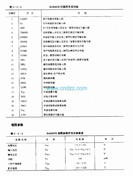
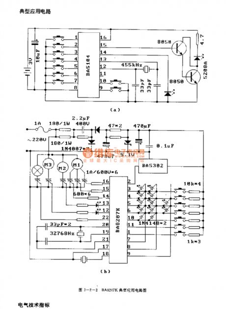
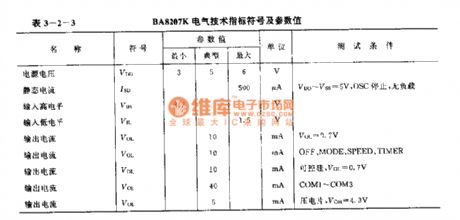
Technology characteristicThree sort: common wind, simulation natural wind and sleep wind.Wind speed is classified to strong, middling and weak.Four-flight progressive timing and a set of absolute color light control function.Pioting control and longitudinal attitude adjust control.Related types are BA5104(infrared remote control transmitting circuit)and BA5302(infrared remote control receiving circuit).22-pin dual-in-line package.
(View)
View full Circuit Diagram | Comments | Reading(738)
Gree KYTA-30B remote control electric fan circuit
Published:2011/7/8 19:36:00 Author:Lena | Keyword: remote control, electric fan
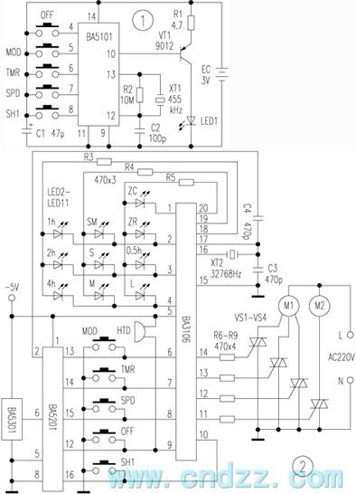
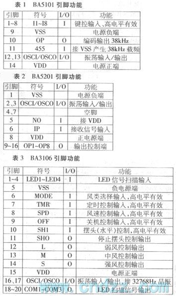
Gree KYTA-30B is a multi-function infrared electric fan, which is with a programmable control circuit BA3106 as the core, and coordinates with a pair of infrared remote control code/encoder BA5101/BA5201. It has the following features: strong, middle, weak wind speed control; common, nature, sleep wind class selection; sleep wind can be auto pre-set in 4 hours; 7.5 hours four-segment progressive timing; a set of independency electric shake function; correct input buzzer prompt and uses 32768Hz crystal oscillator as the time base.
(View)
View full Circuit Diagram | Comments | Reading(783)
adding computer control circuit for common fan
Published:2011/7/8 19:28:00 Author:Lena | Keyword: computer control, common fan
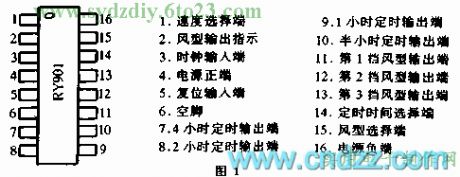

The popular “computer fan” or “electric programmable control fan” on the market, are mostly combinative production of integrated circuit controller and old-fashioned fan. This circuit uses a selling special integrated circuit RY901, refitting a common fan to a multifunction senior fan, suited for wireless hobbyist to make and refit.
The main feature of new type IC is: It brings together switch, timing, adjust speed and simulate nature wind, and has less periphery elements, simple circuit, simple facture.
(View)
View full Circuit Diagram | Comments | Reading(686)
infrared remote control circuit(TR1300/1315,PIC12043)
Published:2011/7/8 22:38:00 Author:Lena | Keyword: infrared, remote control
The same as digital coding circuit, encode outputted by code hopping encoding circuit can be transmitted by infrared ray or radio wave. At the receiving end, modulation signal received by receiving circuit, demodulation circuit is amplified and demodulated, then the code hopping decode chip outputs analyzed channel data, to control relevant circuit by executing circuit. Infrared remote control circuit shown in the figure consists of code hopping chip TR1300/1315 and infrared remote control receiving module PIC12043.
remote control receiving circuit:
infrared receiving demodlation decode and output circuit:
(View)
View full Circuit Diagram | Comments | Reading(516)
simple banausic remote control switch circuit
Published:2011/7/9 8:50:00 Author:Lena | Keyword: simple, banausic, remote control, switch
This remote control switch only uses 5 triodes, the entire circuit can be installed on the 40mm×50mm circuit board to control different electric devices on/off remotely, the circuit is shown in the figure. The remote control emitter is common household appliance remote controller. As long as the receiving control circuit is welded according to the figure, it will be success without debugging.IR is a infrared remote control receiving end, when there is no infrared signal, ① pin outputs high level, when there is a infrared signal, ① pin outputs a series of low level pulse.
(View)
View full Circuit Diagram | Comments | Reading(610)
facility currency infrared remote control receiving circuit
Published:2011/7/8 22:52:00 Author:Lena | Keyword: facility, currency, infrared, remote control, receiving
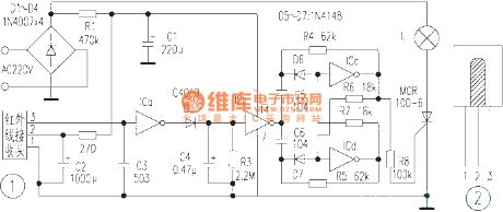
At present, the quantity of TV, VCD, VCR etc infrared remote control emitters is increasing. This design of the circuit aims at their performance, making the remote control emitter to exert another purpose: emit infrared signal, control lighting lamp and the control distance is >8 meters.Circuit principle: This infrared control switch circuit is shown in figure 1, which mainly consists of infrared receiving end and IC4069. When the infrared receiving end is static, the circuit outputs high level. When the circuit receives infrared pulse signal that is sent by remote control emitter, tail edge outputs low level (pulse signal).
(View)
View full Circuit Diagram | Comments | Reading(600)
family satellite and cable television in the common cable and remote control circuit
Published:2011/7/8 22:57:00 Author:Lena | Keyword: family, satellite, cable television, common cable, remote control
Family usually only use satellite receiver aside the TV set to watch satellite television, but it’s difficult in another room. Now, I use former cable television line, mixing the satellite television signal and cable television signal to transfer in the common cable, to realize all the TV sets can watch satellite television in one family. Common cable connecting circuit is shown as figure 1. Satellite receiver RF output end outputs U segment satellite television signal that is amplified by triode VT1, then mix the amplified signal and cable TV signal through 75-3 feedback line.
(View)
View full Circuit Diagram | Comments | Reading(497)
| Pages:206/312 At 20201202203204205206207208209210211212213214215216217218219220Under 20 |
Circuit Categories
power supply circuit
Amplifier Circuit
Basic Circuit
LED and Light Circuit
Sensor Circuit
Signal Processing
Electrical Equipment Circuit
Control Circuit
Remote Control Circuit
A/D-D/A Converter Circuit
Audio Circuit
Measuring and Test Circuit
Communication Circuit
Computer-Related Circuit
555 Circuit
Automotive Circuit
Repairing Circuit