
Index 267
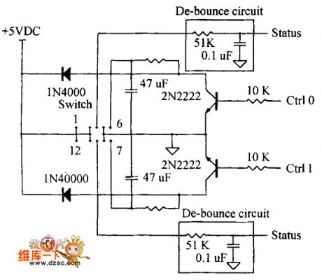
Delphi electronic control system circuit diagram
Published:2011/5/13 2:10:00 Author:Ecco | Keyword: Delphi , electronic control system

View full Circuit Diagram | Comments | Reading(1016)
Sony KV-25G protection circuit
Published:2011/5/12 20:27:00 Author:TaoXi | Keyword: Sony, protection circuit
Sony KV-25G protection circuit (View)
View full Circuit Diagram | Comments | Reading(458)
Low cost temperature controller circuit
Published:2011/5/12 20:40:00 Author:TaoXi | Keyword: Low cost, temperature controller
Low cost temperature controller circuit (View)
View full Circuit Diagram | Comments | Reading(539)
Greenhouse temperature and humidity automatic controller circuit
Published:2011/5/12 20:50:00 Author:TaoXi | Keyword: Greenhouse, temperature, humidity, automatic controller
Greenhouse temperature and humidity automatic controller circuit (View)
View full Circuit Diagram | Comments | Reading(692)
Over-temperature monitoring warning circuit diagram
Published:2011/5/12 1:23:00 Author:Rebekka | Keyword: Over-temperature monitoring warning
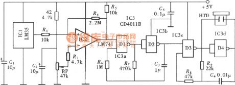
Over-temperature monitoring warning(LM35、LM741) circuit diagram is shown as above.
The over-temperature monitoring alarm circuit uses the integrated circuit temperature sensor as temperature measurement device. It only sets a maximum limiting temperature control points. When the temperature exceeds the limit temperature, the alert sounds, prompting the user to pay attention. The parts of the circuit is shown in the figure. It is composed of the temperature detector, over-temperature monitoring circuit, warning sound occurs and the output circuit. (View)
View full Circuit Diagram | Comments | Reading(1610)
Induction heating automatic control circuit diagram
Published:2011/5/12 20:04:00 Author:Rebekka | Keyword: Automatic control, Induction heating
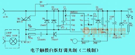
The circuit is mainly made of the specialized chip SM7232. It controls the switching and dimming incandescent lamps by human touch M-point tablets, the maximum load power is 500W.It is better to install the LED near to the touch-chip, so that it can play the role of instruction in the dark. From the human security considerations, it uses two resistors R6 and R7 . (View)
View full Circuit Diagram | Comments | Reading(3390)
Taper protection circuit diagram
Published:2011/5/12 21:38:00 Author:Nicole | Keyword: Taper protection
View full Circuit Diagram | Comments | Reading(514)
Frost Alarm Circuit (2)
Published:2011/5/12 2:19:00 Author:Robert | Keyword: Frost, Alarm
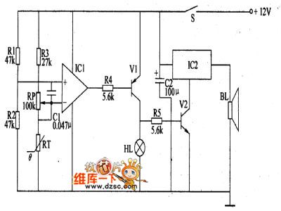
The forst alarm circuit introduced in this example can give the sound and light signal immediately when the frost coming to remind the workers to prepare for anti-frost in time. This device can be widely used in the areas such as agriculture and mining and so on.The circuit's working principle is shown below.This frost alarm circuit is made up by the frost detecting circuit and sound-lignt alarm circuit which is shown in the picture below. The frost detecting circuit is made up by the thermistor RT, resistance R1~R3, potentiometer RP, capacitor C and operational amplifier integrated circuit IC1.The sound-light alarm circuit is made up by resistance R4, R5, transistor V1, V2, alarm alarm indicator lamp HL, sound effect integrated circuit IC2 and speaker BL.When there is no frost, the atmospheric temperature is relatively higher. RT is in low-resistance mode, IC in-phase input port's voltage is higher than the out-phase input port's, and it outputs high voltage level to make V1 and V2 disconnected. So HL does not light and IC2 does not work, BL has no sound.In case of the frost coming, the atmospheric temperature is low and the RT's resistance would rise to make the IC's out-phase input port voltage higer than the in-phase input port's voltage and make its output port's voltage be low voltage level. So V1 and V2 is connected and HL would light, IC2 is electrified to work and BL would have the alarm sound.
(View)
View full Circuit Diagram | Comments | Reading(932)
Mine-used electric coal drill safely using electricity controller
Published:2011/5/11 3:59:00 Author:Nicole | Keyword: electric coal drill, safely using electricity, controller
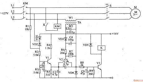
This mine-used electric coal drill safely using electricity controller can use electric drill handle switch to conveniently achieve long distance automatic power failure and power transmission, it greatly reduces the cable charging time and increases the security of using electricity.
The working principle of this circuit
This mine-used electric coal drill safely using electricity controller circuit is composed of trigger control circuit, hold circuit and control implement circuit, it is shown in the figure 8-33.
The trigger control circuit is made of electric drill handle switch S, resistors R1-R5, diodes VD1, VD2, capacitors C1, C2 and transistor V1.
The hold circuit is composed of current transformer TA, capacitors C3-C5, diodes VD3, VD4, resistors R6, R7 and transistor V2.
The control implement circuit consists of resistors R8, R9, capacitor C6, transistor V3, diode VD5, relay K and AC contactor KM.
When S is turned off, the current of L3 phase line disappears, then V2 cuts off, V3 cuts off too, K and KM gives off, M stops turning due to power failure.
(View)
View full Circuit Diagram | Comments | Reading(2580)
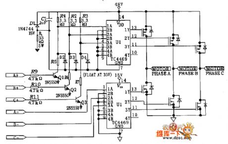
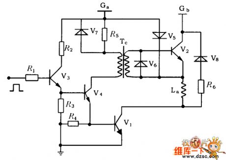
Three phase brushless motor drive circuit diagram
Published:2011/5/12 21:33:00 Author:Nicole | Keyword: Three phase, brushless motor drive
View full Circuit Diagram | Comments | Reading(4087)
Combination protection circuit of constant current current-limiting circuit and disconnection current protection circuit
Published:2011/5/12 21:28:00 Author:Nicole | Keyword: Combination protection, constant current, current-limiting, disconnection, current protection
View full Circuit Diagram | Comments | Reading(676)
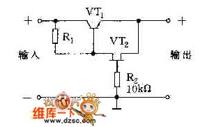
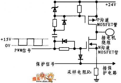
Protection circuit diagram adopted field effect transistor
Published:2011/5/12 21:34:00 Author:Nicole | Keyword: field effect transistor, protection
View full Circuit Diagram | Comments | Reading(493)
Typical constant current overcurrent protection circuit diagram
Published:2011/5/12 21:31:00 Author:Nicole | Keyword: constant current, overcurrent protection
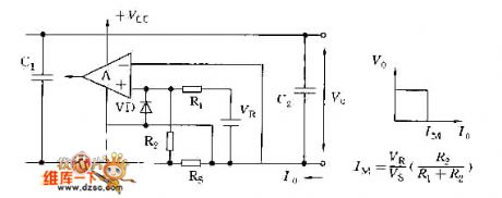
View full Circuit Diagram | Comments | Reading(804)
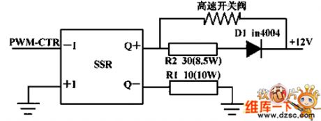
Hydraulic slipway PWM microcomputer control drive circuit diagram
Published:2011/5/12 20:47:00 Author:Nicole | Keyword: Hydraulic slipway, PWM, microcomputer, control drive
View full Circuit Diagram | Comments | Reading(586)
UC3637 two phase stepping motor driver drive circuit diagram
Published:2011/5/12 20:58:00 Author:Nicole | Keyword: two phase, stepping motor, driver drive
View full Circuit Diagram | Comments | Reading(1317)
Stepping motor drive circuit diagram
Published:2011/5/12 20:54:00 Author:Nicole | Keyword: Stepping motor drive
View full Circuit Diagram | Comments | Reading(535)
Optical switch drive circuit diagram
Published:2011/5/12 20:59:00 Author:Nicole | Keyword: Optical switch drive
View full Circuit Diagram | Comments | Reading(772)
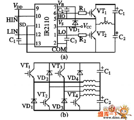
Bootstrap IR2110 integrated drive circuit diagram
Published:2011/5/12 20:45:00 Author:Nicole | Keyword: Bootstrap, integrated drive
View full Circuit Diagram | Comments | Reading(1827)
Long time delay timer controller (CD4060, CD4518, CD4069) circuit diagram
Published:2011/5/12 6:16:00 Author:Rebekka | Keyword: Long time delay timer controller
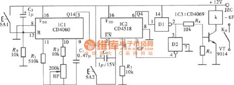
Long time delay timer controller (CD4060, CD4518, CD4069) circuit composed of CD4060, CD4518 andCD4069.
It is a time base circuit composed of a CD4060. The timing time base pulse generated by the circuit passes the internal divider and outputs time base signal. And then passes the peripheral frequency divider circuit to obtain the required timing control time. (View)
View full Circuit Diagram | Comments | Reading(4382)
Positive and negative pulse delay circuit compoed of CD4013
Published:2011/5/12 6:33:00 Author:Rebekka | Keyword: Positive and negative pulse delay
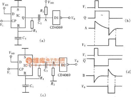
In the digital circuits and automatic control circuit, sometimes you need to delay the inputed pulse signal for a while and then output the signal. This can accommodate the needs of post-level control circuit. One of the application scheme is to use the pulse delay circuit composed of CD4013. The positive and negative pulse delay circuit compoed of CD4013 is shown as above. (View)
View full Circuit Diagram | Comments | Reading(4808)
| Pages:267/312 At 20261262263264265266267268269270271272273274275276277278279280Under 20 |
Circuit Categories
power supply circuit
Amplifier Circuit
Basic Circuit
LED and Light Circuit
Sensor Circuit
Signal Processing
Electrical Equipment Circuit
Control Circuit
Remote Control Circuit
A/D-D/A Converter Circuit
Audio Circuit
Measuring and Test Circuit
Communication Circuit
Computer-Related Circuit
555 Circuit
Automotive Circuit
Repairing Circuit