
Index 247
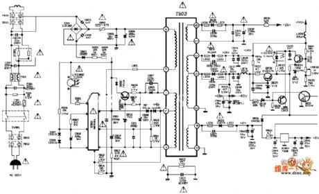
tcl 2580fl TV power supply circuit diagram
Published:2011/4/1 4:01:00 Author:Nicole | Keyword: tcl, TV power supply
View full Circuit Diagram | Comments | Reading(3538)
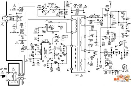
tcl 2980db TV power supply circuit diagram
Published:2011/4/1 4:01:00 Author:Nicole | Keyword: TV power supply, tcl
View full Circuit Diagram | Comments | Reading(5573)
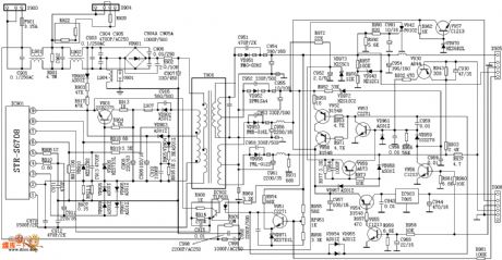
Venus d2902 TV power supply circuit diagram
Published:2011/4/1 4:01:00 Author:Nicole | Keyword: TV power supply, Venus
View full Circuit Diagram | Comments | Reading(1911)
Adjustable voltage socket circuit
Published:2011/4/13 4:14:00 Author:Nicole | Keyword: voltage, socket
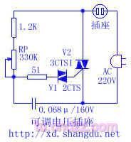
As shown in the figure, it can be usedfor thermoregulation(electric iron), dimming(lamp) and speed regulation(motor), When you want to use it, just put the plug in the socket, it is very convenient. V1 is bi-direction diode, V2 is 3CTSI TRIAC, adjusting RP can change the voltage of socket. (View)
View full Circuit Diagram | Comments | Reading(648)
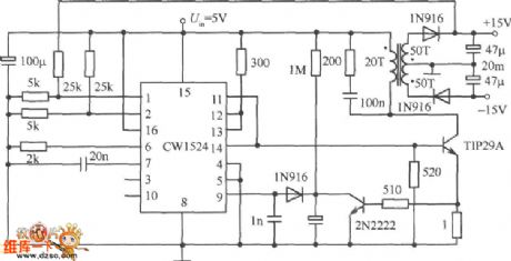
Single-ended flyback integrated switching power supply circuit diagram
Published:2011/3/30 3:20:00 Author:Nicole | Keyword: integrated switching power supply, Single-ended flyback
View full Circuit Diagram | Comments | Reading(828)
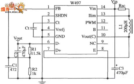
Boost switching regulator application circuit diagram
Published:2011/3/30 3:14:00 Author:Nicole | Keyword: switching regulator
View full Circuit Diagram | Comments | Reading(776)
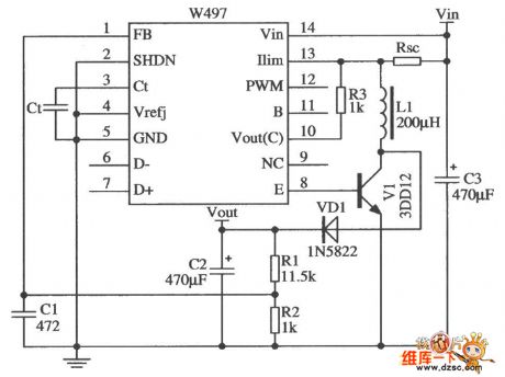
Output voltage polarity reversal application circuit diagram composed of components and W497
Published:2011/3/30 3:10:00 Author:Nicole | Keyword: Output voltage, component
View full Circuit Diagram | Comments | Reading(813)
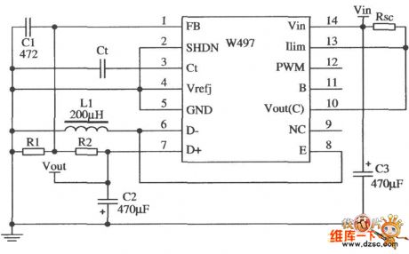
Step-expansion flow circuit diagram composed of W497
Published:2011/3/30 3:10:00 Author:Nicole | Keyword: step-expansion flow
View full Circuit Diagram | Comments | Reading(526)
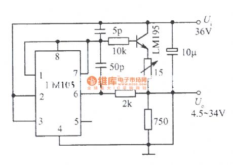
4.5~34V, 1A adjustable regulated power supply composed of LM105, LM195 integrated power tube
Published:2011/4/13 4:24:00 Author:Nicole | Keyword: regulated power supply, integrated power tube
View full Circuit Diagram | Comments | Reading(655)
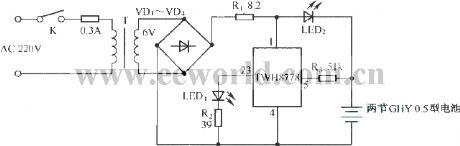
Charger circuit composed of MAX1501
Published:2011/4/17 8:27:00 Author:Nicole | Keyword: charger
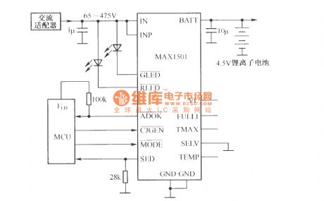
MAX1501 is a new type charge chip, it adopts MAX1501 torealize charger's simple design. MAX1501 can be set to single lithium ion battery charge controller, it also can be set to 3 nodes serial nicad, Ni-MH battery charge controller. The charger circuit composed of MAX1501 is shown as below.
(View)
View full Circuit Diagram | Comments | Reading(1256)
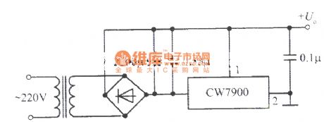
Fixed positive output integrated voltage regulator
Published:2011/4/6 4:07:00 Author:Nicole | Keyword: positive output, integrated voltage regulator
View full Circuit Diagram | Comments | Reading(497)
Optical coupling v/F transformation circuit
Published:2011/4/12 4:36:00 Author:Nicole | Keyword: optical coupling, transformation
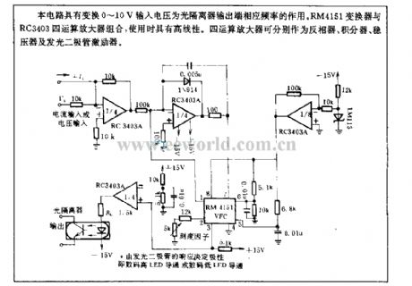
The circuit has the function of changing 0~10V input voltage into the frequency of optical isolator output terminal. Combined RM4151 converter with RC3403 four operational amplifiers, they will have high linearity. The four operational amplifiers are inverter, integrator, regulator and LED exciter. (View)
View full Circuit Diagram | Comments | Reading(686)
Simple Ni-Cd battery automatic charger circuit2
Published:2011/4/18 4:49:00 Author:Nicole | Keyword: Ni-Cd battery, automatic pulse charger
View full Circuit Diagram | Comments | Reading(632)
Simple Ni-Cd battery automatic charger circuit1
Published:2011/4/18 4:49:00 Author:Nicole | Keyword: Ni-Cd battery, automatic pulse charger
View full Circuit Diagram | Comments | Reading(830)
0V to 50V regulated voltage power supply circuit
Published:2011/3/30 2:13:00 Author:muriel | Keyword: 0V to 50V, regulated voltage power supply
View full Circuit Diagram | Comments | Reading(632)
1 to 30V、5A regulated voltage power supply circuit
Published:2011/3/30 2:14:00 Author:muriel | Keyword: 1 to 30V, 5A, regulated voltage power supply
View full Circuit Diagram | Comments | Reading(750)
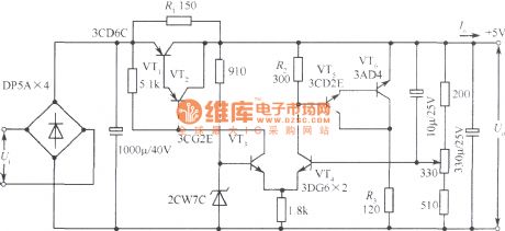
5V Collector output serial and parallel combination regulated power supply circuit
Published:2011/4/14 1:04:00 Author:muriel | Keyword: 5V , Collector output, serial and parallel combination , regulated power supply
View full Circuit Diagram | Comments | Reading(624)
12V/5A regulated power supply circuit
Published:2011/4/18 2:44:00 Author:muriel | Keyword: 12V/5A , regulated power supply
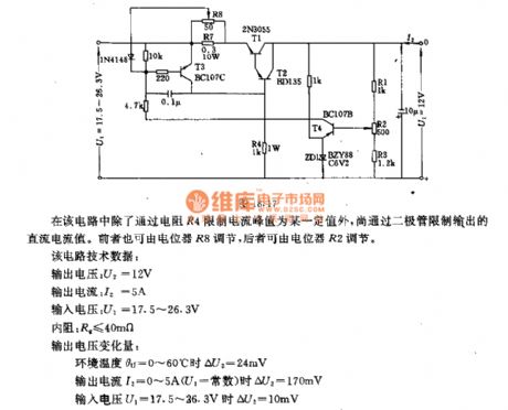
In the circuit the current peak value is a certain value gothrough the limit of the resistor R4, and the output of DC current value is limited by the diodes. The former can adjust by potentiometer R8, the latter can beadjusted by potentiometer R2.
The main technical data: output voltage:U2=12V output current:I2=5A input voltage:U1=17.5V~26.3V internal resistance:R2≤40mΩ output voltage variable quantity: When output voltage U1=17.5V~26.3V, ΔU2=10mV; when output current I2=0A~5A(U1=constant), ΔU2=170mV; ambient temperature θu=0°C~60°C, ΔU2=24mV.
(View)
View full Circuit Diagram | Comments | Reading(2523)
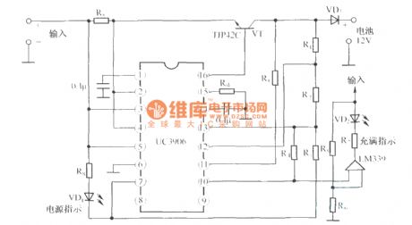
The circuit diagram of 12V sealed valve-regulated lead acid battery dual-level float charger UC3960
Published:2011/4/14 21:54:00 Author:muriel | Keyword: 12V , sealed valve-regulated, lead acid battery , dual-level float, charger
View full Circuit Diagram | Comments | Reading(2047)
BQ2057 charging flow chart
Published:2011/4/14 1:20:00 Author:muriel | Keyword: charging flow chart

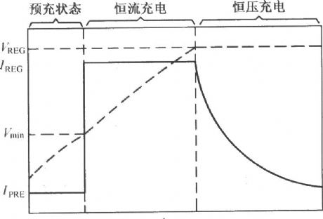
The BQ2057 typical charging characteristic curve:
(View)
View full Circuit Diagram | Comments | Reading(750)
| Pages:247/291 At 20241242243244245246247248249250251252253254255256257258259260Under 20 |
Circuit Categories
power supply circuit
Amplifier Circuit
Basic Circuit
LED and Light Circuit
Sensor Circuit
Signal Processing
Electrical Equipment Circuit
Control Circuit
Remote Control Circuit
A/D-D/A Converter Circuit
Audio Circuit
Measuring and Test Circuit
Communication Circuit
Computer-Related Circuit
555 Circuit
Automotive Circuit
Repairing Circuit