ACE9030

Features: · Low Power Low Voltage (3·6 to 5·0 V) Operation· Serial Bus Controlled Power Down Modes· Simple Programming Format· Reference Crystal Oscillator· Frequency Multiplier for LO2 Signal· 8.064 MHz Output for External Microcontroller· Main Synthesiser with Fractional-N Option· Auxiliary Synt...

product image

ACE9030 Picture
SeekIC No. : 004267325 Detail

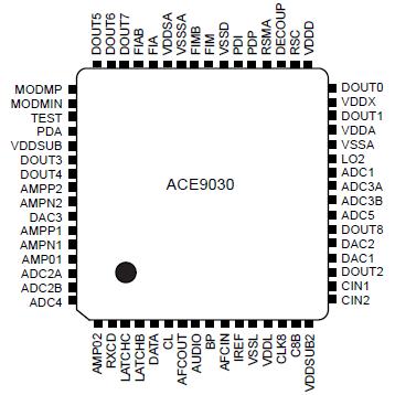
ACE9030: Features: · Low Power Low Voltage (3·6 to 5·0 V) Operation· Serial Bus Controlled Power Down Modes· Simple Programming Format· Reference Crystal Oscillator· Frequency Multiplier for LO2 Signal· 8.06...

floor Price/Ceiling Price

Part Number:
ACE9030
Supply Ability:
5000

Price Break

  • Qty
  • 1~5000
  • Unit Price
  • Negotiable
  • Processing time
  • 15 Days
Total Cost: $ 0.00

SeekIC Buyer Protection PLUS - newly updated for 2013!

  • Escrow Protection.
  • Guaranteed refunds.
  • Secure payments.
  • Learn more >>

Month Sales

268 Transactions

Rating

evaluate  (4.8 stars)

Upload time: 2024/4/26

Payment Methods

All payment methods are secure and covered by SeekIC Buyer Protection PLUS.

Notice: When you place an order, your payment is made to SeekIC and not to your seller. SeekIC only pays the seller after confirming you have received your order. We will also never share your payment details with your seller.
Product Details

Description


Features:

· Low Power Low Voltage (3·6 to 5·0 V) Operation
· Serial Bus Controlled Power Down Modes
· Simple Programming Format
· Reference Crystal Oscillator
· Frequency Multiplier for LO2 Signal
· 8.064 MHz Output for External Microcontroller
· Main Synthesiser with Fractional-N Option
· Auxiliary Synthesiser
· Main Synthesiser Speed-up Options
· FM Discriminator for 450 kHz or 455 kHz I.F. Signal
· Radio System Control Interface
· Part of the ACE Integrated Cellular Phone Chipset
· TQFP 64 pin 0.4 mm and 0.5 mm pitch packages


Application

· AMPS and TACS Cellular Telephone
· Two-way Radio Systems


Pinout

  Connection Diagram


Specifications

Supply voltage from ground ......... 0.3 V to + 6.0 V
(any VDD to any VSS)
Supply voltage difference ............. 0.3 V to + 0.3 V
(any VDD to any other VDD)
Input voltage ..................VSS 0.3 V to VDD + 0.3 V
(any input pin to its local VSS and VDD)
Output voltage ...............VSS 0.3 V to VDD + 0.3 V
(any output pin to its local VSS and VDD)
Storage temperature ............. 55 °C to + 150 °C
Operating temperature ............ 40 °C to + 85 °C

These are not the operating conditions, but are the absolute limits which if exceeded even momentarily may cause permanent damage. To ensure sustained correct operation the device should be used within the limits given under Electrical Characteristics.

To avoid any possibility of latch-up the substrate connec-tions VDDSUB and VDDSUB2 must be the most positive of all VDD's at all times including during power on and off ramping. As the current taken through these VDD's is significantly less than through the other VDD's this requirement can be easily met by directly connecting all VDD pins to a common point on the circuit board but with the decoupling capacitors distributed to minimise cross-talk caused by common mode currents. If low value series resistors are to be included in the VDD connections,with decoupling capacitors by the ACE9030 pins to further reduce interference, the VDDSUB and VDDSUB2 pins should not have such a resistor in order to guarantee that their voltage is not slowed down at power-on. Power switches to DOUT0 and DOUT1 are supplied from VDDX and are specified for a total current of up to 40 mA so any resistor in the VDDX connection must be very low, around 1W, in order to avoid excessive voltage drop; it is recommended that this supply
has no series resistor. These two methods are shown in circuit diagrams, figures 4 and 5. In both circuits the main VDD must also have good decoupling.


Description

ACE9030 is a combined radio interface circuit and twin synthesiser, intended for use in a cellular telephone.

The radio interface section of ACE9030 contains circuits to monitor and control levels such as transmit power in the telephone, circuits to demodulate the frequency modulated signal to audio, and a crystal oscillator with a frequency multiplier.

The Main synthesiser ACE9030 has normal and fractional-N modes both with optional speed-up to select the desired channel. The Auxiliary synthesiser is used for the transmit-receive offset and for modulation.

Both sections of ACE9030 are controlled by a serial bus and have software selected power saving modes for battery economy. The circuit techniques used have been chosen to minimise external components and at the same time give very high performance.


Customers Who Bought This Item Also Bought

Margin,quality,low-cost products with low minimum orders. Secure your online payments with SeekIC Buyer Protection.
Optical Inspection Equipment
Potentiometers, Variable Resistors
Cables, Wires
Crystals and Oscillators
Batteries, Chargers, Holders
Soldering, Desoldering, Rework Products
View more