
D/A Converter
Index 2
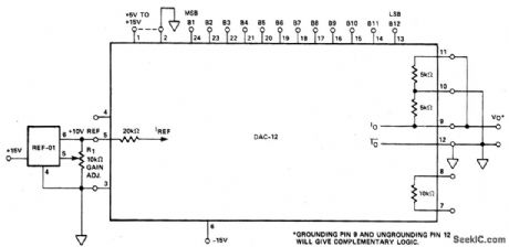
RESISTOR_TERMINATED_DAC0_TO_5_V_OUTPUT
Published:2009/6/26 2:15:00 Author:May
View full Circuit Diagram | Comments | Reading(956)
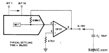
FAST_VOLTAGE_OUTPUT_D_A_CONVERTER
Published:2009/6/26 2:11:00 Author:May
View full Circuit Diagram | Comments | Reading(806)
10_BIT_D_A_CONVERTER
Published:2009/6/26 2:10:00 Author:May
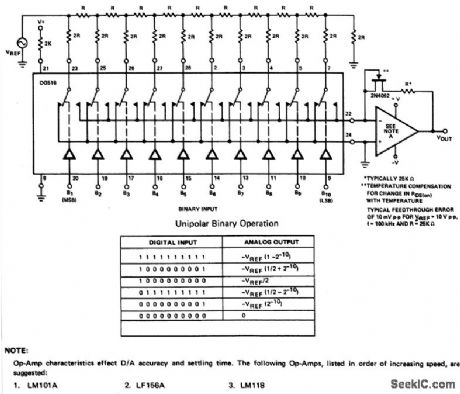
0p-Amp characteisties effect D/A accuracy and setding time. The following Op-Amps, listed in order of increasing speed, are suggested:1.LM101A 2.LF156A 3.LM118 (View)
View full Circuit Diagram | Comments | Reading(989)
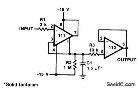
14_BIT_BINARY_D_A_CONVERTERUNIPOLAR
Published:2009/6/26 2:02:00 Author:May
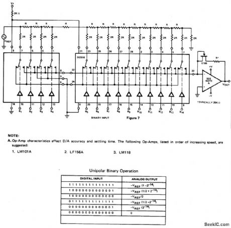
View full Circuit Diagram | Comments | Reading(790)
OCTAL_D_A_CONVERTER
Published:2009/6/23 2:00:00 Author:May
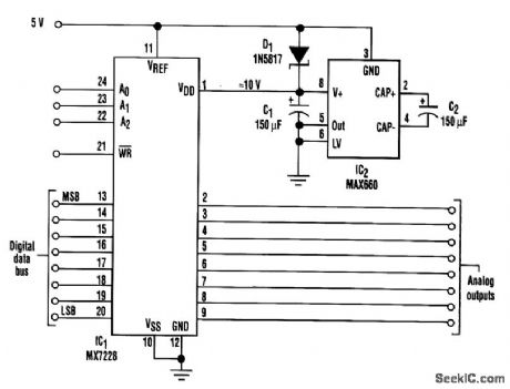
This octal digital-to-analog converter operates on 5V and provides eight output voltages, each digitally adjustable from supply rail to supply rail (0 to 5V). Each output's resolution is 20 mV/LSB. The DAC chip (IC1) requires 3.5V of headroom between its VDD and reference voltages. However, a voltage-doubler charge pump (IC2) removes this limitation by generating an approximate 10-V supply for VDD. All of the converter references are connected to the 5-V supply. IC2 doubles the 5-V input to an unregulated 10-V output that has an output impedance of less than 10Ω. It can deliver 100 rnA, which enables the eight DACs to issue their maximum output currents simultaneously (8×5 mA = 40 mA). (View)
View full Circuit Diagram | Comments | Reading(976)
12_BIT_DAC
Published:2009/6/22 23:52:00 Author:May
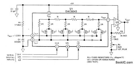
This circuit uses an Analog Devices DAC-8043 12-bit multiplying DAC The output will be D/4096×Vref where D is the numerical value of the digital input word(0 to 4095) Vref is 1.235 volts in this cicuit (View)
View full Circuit Diagram | Comments | Reading(0)
DIGITAL_TO_ANALOG_CONVERTER
Published:2009/6/17 3:56:00 Author:May
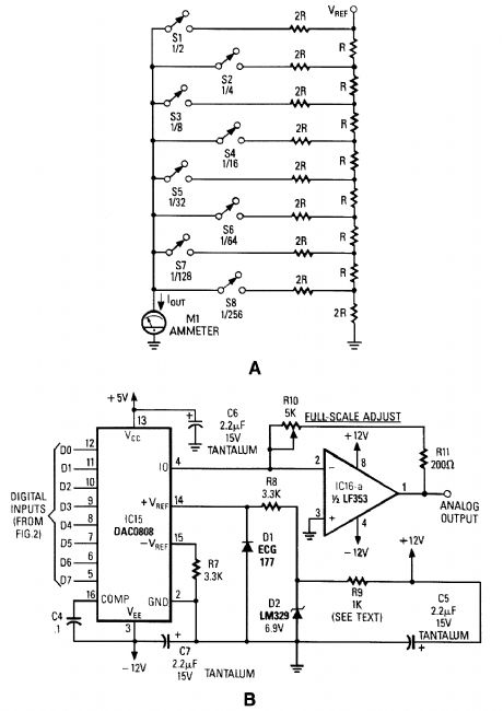
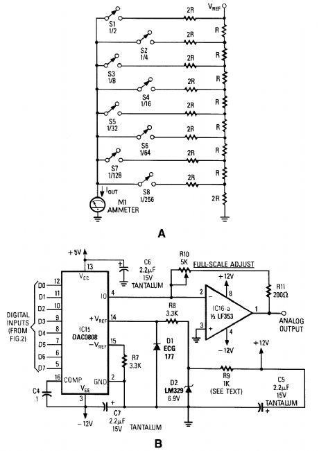
Figure A is an R/2R resistor ladder. Each switch that is closed increases the amount of current at Iout. A simple channel A/D converter is shown in Fig. B. The voltage reference (D2) is common to all channels, but the value of the dropping resistor (R9) varies as the number of DACs installed in the system. IC15 is a DAC0808 A/D converter chip. IC16A is an op amp to interface the output current from the D/A convert to an analog voltage output. (View)
View full Circuit Diagram | Comments | Reading(1217)
| Pages:2/2 12 |
Circuit Categories
power supply circuit
Amplifier Circuit
Basic Circuit
LED and Light Circuit
Sensor Circuit
Signal Processing
Electrical Equipment Circuit
Control Circuit
Remote Control Circuit
A/D-D/A Converter Circuit
Audio Circuit
Measuring and Test Circuit
Communication Circuit
Computer-Related Circuit
555 Circuit
Automotive Circuit
Repairing Circuit