
Index 203
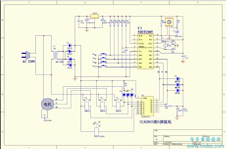
The massager circuit of SCH
Published:2011/6/10 1:27:00 Author:Seven | Keyword: massager circuit
The massager circuit of SCH (View)
View full Circuit Diagram | Comments | Reading(530)
The USB multi-media of 2.5W+2.5W
Published:2011/6/10 1:28:00 Author:Seven | Keyword: USB multi-media
Brief description: it doesn't need an external power supply or a sound card, and the cost is 20 yuan.
(View)
View full Circuit Diagram | Comments | Reading(545)
The common sound circuit of color TV: TDA7057
Published:2011/6/10 1:29:00 Author:Seven | Keyword: sound circuit
Pin functions and reference voltage of TDA7057: 1-pin:0~1v----DC sound volume control 12-pin:0v----empty3-pin:2v----input 14-pin:19v----power supply5-pin:2v----input 26-pin:0v----signal GND7-pin:0~1v--DC sound volume control 28-pin:8.6v----positive output 29-pin:0v----power amplifier GND 210-pin:8.6v----negative output 111-pin:8.6v----negative output 212-pin:0v----power amplifier GND13-pin:8.6v----positive output 1 (View)
View full Circuit Diagram | Comments | Reading(1776)
The common sound circuit of color TV: TDA2009
Published:2011/6/10 1:29:00 Author:Seven | Keyword: sound circuit, color TV
TDA2009I-pin:1.2v----left channel input; 2-pin:0.8v----left channel feedback; 3-pin:12v----mute/noisy;4-pin:0.8v----right channel feedback; 5-pin:1.2v----right channel feedback; 6-pin:0v----ground; 7-pin:0v----empty; 8-pin:12.4v----right channel output; 9-pin:24v----power supply; 10-pin:12.4v----left channel output;11-pin:---- (View)
View full Circuit Diagram | Comments | Reading(696)
The common sound circuit of color TV: TDA1521
Published:2011/6/10 1:30:00 Author:Seven | Keyword: sound circuit
This circuit is from Changhong C2191, which is of OTL dual-channel connectionPin functions and reference voltage of TDA1521:1-pin:11v----backward input(L channel signal input);2-pin:11v----forward input 1;3-pin:11v----reference 1(it's 0v when it is in OCL connection, and it's 1/2Vcc when it's in OTL connection );4-pin:11v----ouput 1(L channel signal output);5-pin:0v----negative power supply input(it connects with the earth when it is in OTL connection ); 6-pin:11v----output 2(R channel signal output);7-pin:22v----positive power supply input; 8-pin:11v----positive input (View)
View full Circuit Diagram | Comments | Reading(601)
The common sound circuit of color TV: TDA1013B
Published:2011/6/10 1:30:00 Author:Seven | Keyword: sound circuit
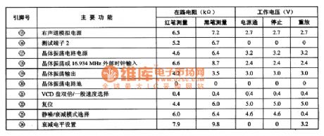
Pin functions and reference voltage of TDA10131-pin:0v----earth;2-pin:7.7v----sound output; 3-pin:16v----power supply; 4-pin:13.5v----power supply; 5-pin:0.3v----power supply; 6-pin:6.7v----pre-output; 7-pin:2.8v----sound volume control; 8-pin:1.9v----audio input; 9-pin:0v----earth (View)
View full Circuit Diagram | Comments | Reading(614)
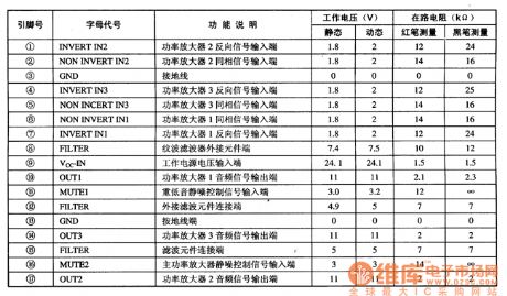
The common sound circuit of color TV: TA8218AH
Published:2011/6/10 1:31:00 Author:Seven | Keyword: sound circuit, color TV
Pin functions and reference voltage of TA8218AH1-pin:1.9v----backward input terminal; 2-pin:3-pin:0v----earth; 4-pin:1.9v----backward input terminal;5-pin:2.1v----heavy low-frequency audio signal input;6-pin:2.1v----L channel audio signal input;7-pin:1.9v----backward input terminal;8-pin:8.9v----filter;9-pin:26v----power supply; 10-pin:13v----L channel audio signal output; 11-pin:4.7v----mute;12-pin:4.5v----empty;13-pin:0v----earth; 14-pin:13v----heavy low-frequency audio signal output (View)
View full Circuit Diagram | Comments | Reading(679)
Sound circuit: AN5265
Published:2011/6/10 1:32:00 Author:Seven | Keyword: Sound circuit
Pin functions and reference voltage of AN52651-pin:12V----pre-stage power supply; 2-pin:5v----audio signal input terminal;3-pin:0v----mute control terminal(it's mute when it is in a high LEV);4-pin:0.1V----input terminal of sound volume control voltage;5-pin:7v----wave filter; 6-pin:7.4v----negative feedback input pole; 7-pin:0v----earth; 8-pin:7.5v---- the output pole of power amplifier; 9-pin:15-----power supply of power amplifier (View)
View full Circuit Diagram | Comments | Reading(712)
The dual sound door bell without battery
Published:2011/6/10 1:32:00 Author:Seven | Keyword: door bell
47.The dual sound door bell without batteryAs the popularity rate of phones is higher and higher, more and more homes have domestic phones, however, usage rate is low, therefore, it's economic to use the 48v(60v) DC current of phones as the working energy. Now we introduce a dual sound door bell without battery, the circuit principle is shown in the figure. From the figure, we can see that the circuit is changed from the common circuits of phone rings. a and b are the positive and negative poles of phone wires, respectively.
(View)
View full Circuit Diagram | Comments | Reading(554)
The 875p computer main board circuit (094)
Published:2011/6/10 1:33:00 Author:Seven | Keyword: main board
View full Circuit Diagram | Comments | Reading(637)
The switch power supply circuit of single chip microcomputers and developing devices
Published:2011/6/10 1:34:00 Author:Seven | Keyword: power supply circuit, single chip microcomputers
This text is to introduce a switch power supply which is used in the developing devices of single chip microcomputers or lab electric devices. This circuit characterizes stable output, adjustable voltage, small size, steady functions and so on. The output switch power supply output is 1.8A, the output voltage ranges +15v~+5v which can be set, and the input voltage is fit for the power supply of AC90v~240v 50/60HZ, so it can provides with power for lab electric experiment measuring devices, and it can also be used to charge the battery of 6v/12v.
(View)
View full Circuit Diagram | Comments | Reading(720)
integrated circuit typical application circuit
Published:2011/5/15 1:01:00 Author:John | Keyword: Typical application circuit, integrated circuit
 (View)
View full Circuit Diagram | Comments | Reading(663)
LDQ852-1Integrated inside circuit box circuit
Published:2011/5/27 7:10:00 Author:John | Keyword: Integrated circuit, inside circuit box

LDQ852-1 integrated circuit mainly consists of an audio oscillator Fl and a frequency divider with grade four trigger. Power regulator II can regulate the power voltage between 3.5V-4.2V, which is able to actuate vibrato generator F2. Vibrato generator F2 is a low frequency oscillator, whose external components determine the frequency of the vibrato. Power regulator I can regulate the power voltage between 3.8V-4.5V, which is used to drive the scale generator and requency divider to work. The inside circuit box circuit has been shown.
(View)
View full Circuit Diagram | Comments | Reading(503)
The integrated amplifier circuit of TDA6107JF single chip video
Published:2011/6/4 2:27:00 Author:qqtang | Keyword: amplifier circuit, single chip
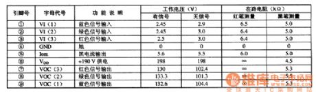
TDA6107JF is an integrated amplifier circuit of TDA6107JF single chip video, which is widely used in all kinds of local and imported big screen color TV as the terminal amplifier. 1.function features TDA6107JF contains a video amplifier circuit(i.e R,G and B, 3 ways of primary colour amplifier), black current generating circuit and other additional function circuits, etc.
2.pin functions and dataTDA6107JF is in a 9-pin single line package, whose pin functions and data are listed in Table 1.Table 1. Pin functions and data of TDA6107JF
(View)
View full Circuit Diagram | Comments | Reading(1927)
SSM2250 multi-function low-power amplifier integrated circuit
Published:2011/6/10 0:54:00 Author:qqtang | Keyword: multi-function, low-power amplifier
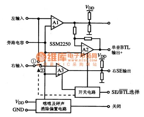
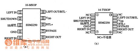
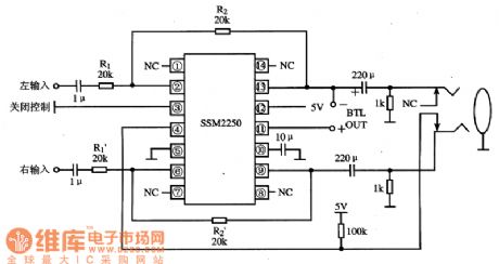
1.function featuresSSM2250 includes 3 full amplitude(output amplitude value is close to that of power supply) computing amplifiers, kluck and Ping sound removing bias circuit and switch control circuit, etc. Its internal circuit is shown in the figure.
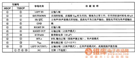
The internal circuit of SSM22502.pin functionsSSM2250 has two kinds of packages: 10-pin MSOP and TSSOP, whose pin sequence is shown in the figure, and the two packages with their relationship and the pin functions are listed in the table.
(View)
View full Circuit Diagram | Comments | Reading(779)
SM5875BM—the D/A shift integrated circuit
Published:2011/6/10 0:56:00 Author:qqtang | Keyword: D/A shift, integrated circuit
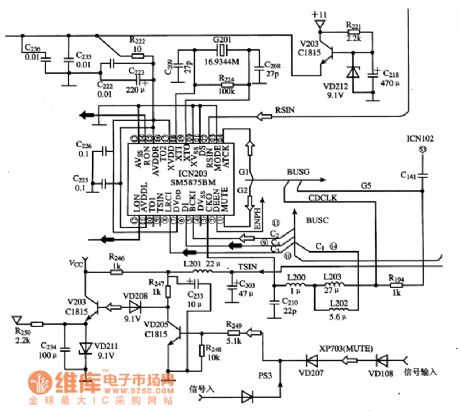
1.function featuresSM5875BM includes 8-time over sampling digital filter and stimulating signal low-pass filter, which consists of serial data input connector, digital filter diminish control circuit, 3 stage noise rectifier circuit, attenuation counter, sequence controller, PWM data generator, clock generating circuit and analog signal low-pass filter, etc. Its functions include digital signal deemphasis, digit or volume attenuation, silence/mute, standard/multiple mode selecting and low-voltage power supply. Its internal circuit is shown in the figure.
(View)
View full Circuit Diagram | Comments | Reading(1585)
TDA381—the integrated circuit of the SRS stereo effect process
Published:2011/6/10 0:57:00 Author:qqtang | Keyword: integrated circuit, SRS stereo
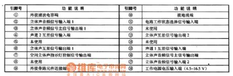
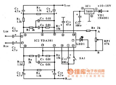
TDA381 is an integrated circuit of the SRS stereo effect process produced by Philips, which is widely used in all kinds of stereo systems.1.function featuresTDA381 can switch the single channel signal into the analog stereo sound signal, which works in the conducting state of the stereo channel, and it can also work in the space stereo sound state.2.pin functions and dataTDA381 is in 18-pin dual in-line package, whose pin functions are listed in Table 1.Table 1. Pin functions of TDA381
Figure 1. The typical application circuit of TDA381
(View)
View full Circuit Diagram | Comments | Reading(1517)
TA8218AH--the 3 channel audio power amplifier integrated circuit
Published:2011/6/9 21:02:00 Author:qqtang | Keyword: audio power amplifier, integrated circuit

TA8218AH is the 3 channel audio power amplifier integrated circuit, produced by Toshiba, which is widely used in the multimedia stereo, domestic stereo, car stereo and TV stereo, etc.1.functions featuresTA8218AH contains 3 lines of same-function audio power amplifier circuits, and it also has functions of silence/mute protection and over heat/voltage protection, etc.2. Pin functions and dataTA8218AH is in 17-pine package, whose pin functions and data are listed in table 1.Table 1. Pin functions and data of TA8218AH
(View)
View full Circuit Diagram | Comments | Reading(4012)
the circuit of zero cross detection
Published:2011/5/27 8:20:00 Author:Ariel Wang | Keyword: zero cross , detection
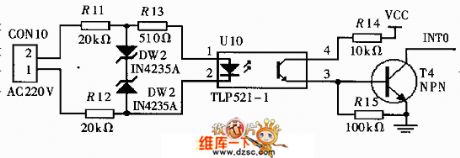
The AC 220V goes to branch current circuit by resistor . Then the branch voltage goes to photocoupling.Let's suppose we input line-to-neutral voltage A .When line-to-neutral voltage A is converting from negative half period to positive half period. It will generates the pulse on the trailing edge.The pulse goes to ADμC812's INTO pin.That makes the system enter the suspending progress.When the micro system entering the suspending progress,it will give a sampling command. And it will read the value reactive current Iqm.The reactive current is A's reactive current.It will reach the max value through 1/4 cycle.At this time,if you sample the voltage,you will get UM. If UM=1.414U,you can get the virtual value U of the voltage.
(View)
View full Circuit Diagram | Comments | Reading(3369)
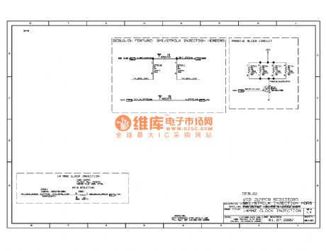
Projectile Speed Test Circuit Diagram
Published:2011/5/20 20:57:00 Author:leo | Keyword: Projectile Speed Test Circuit Diagram, HCT4060, 4096, MOSFET
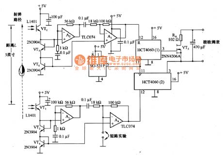
The picture shows a projectile speed test circuit. In the circuit, VT1 and VT2 are phototransistors. Projectile speed begins to be tested when the projectile passes through VT1. When projectile shades VT1, it can be considered as adding 500μV pulse to non-inverting input of A1. The pulse is amplified and reversed through A1 and A4 and offer starting impulse for HCT4060(2)-the 14 bits asynchronous counter. After this, the path of projectile is calculated again from zero and the speed will be calculated by 250ns resolution. At the same time, when projectile reaches VT2, it begins to test HCT4060(1) to test the destination of the projectile. (View)
View full Circuit Diagram | Comments | Reading(1369)
| Pages:203/250 At 20201202203204205206207208209210211212213214215216217218219220Under 20 |
Circuit Categories
power supply circuit
Amplifier Circuit
Basic Circuit
LED and Light Circuit
Sensor Circuit
Signal Processing
Electrical Equipment Circuit
Control Circuit
Remote Control Circuit
A/D-D/A Converter Circuit
Audio Circuit
Measuring and Test Circuit
Communication Circuit
Computer-Related Circuit
555 Circuit
Automotive Circuit
Repairing Circuit