
Index 219
ES4108-super VCD decoding integrated circuit
Published:2011/5/13 12:14:00 Author:Borg | Keyword: decoding, integrated circuit
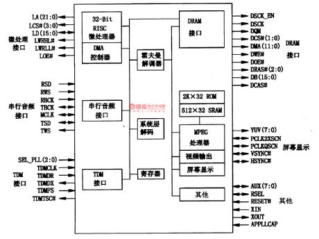
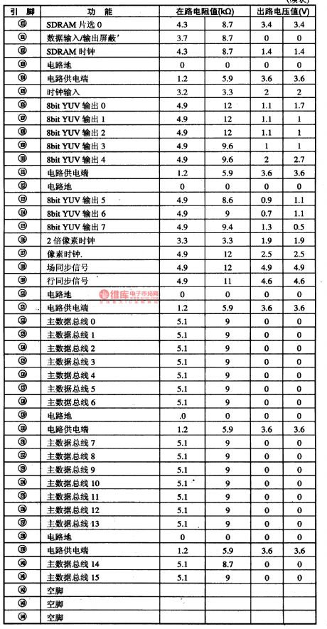
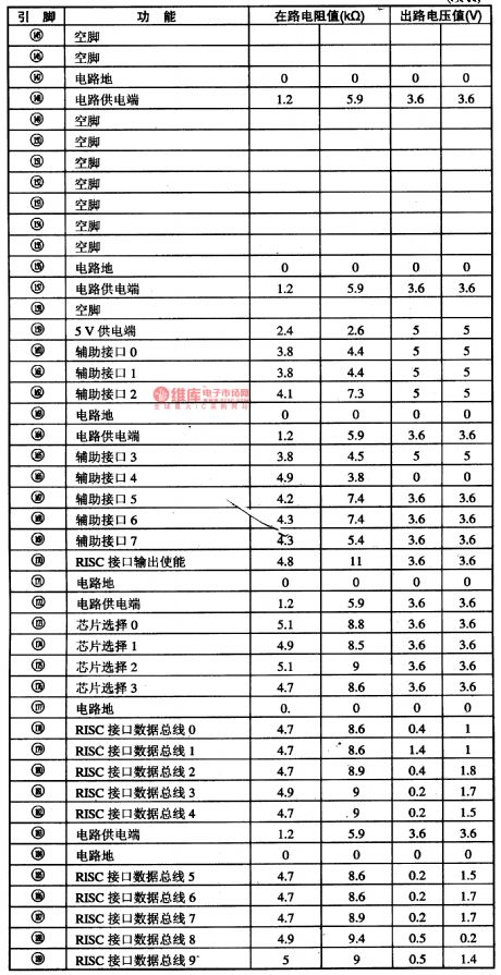
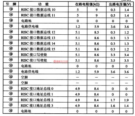
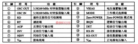
ES4108is a integrated decoding circuit of single door which is specially produced for VCD players by ESS Corp., USA.1.function featuresES4108 can decode SVCD and couple with VCD, in which there are simplified assemble RISC micro-processors of 32 bit orders and 32 bit data. It is based on the multimedia processor, and contains audio and video systems, and computing function chips of Hall decoding.
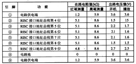
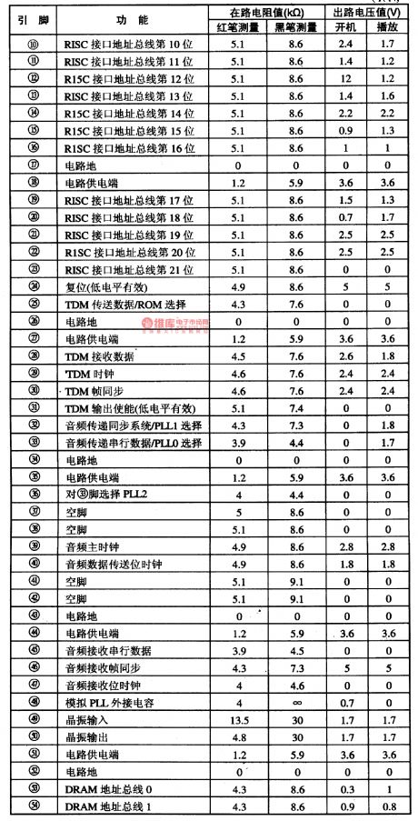
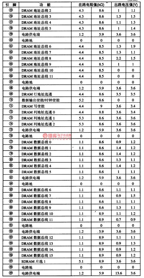
Table 1-1 the internal circuit of ES41082.pin functions and data
(View)
View full Circuit Diagram | Comments | Reading(762)
FX602-The integrated FSKdemodulation circuit of wireless phones
Published:2011/5/13 7:57:00 Author:Borg | Keyword: FSK, demodulation, wireless phones
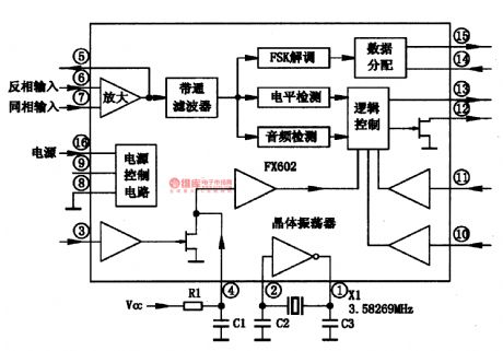
FX602 is an integrated frequency shift keying(FSK) demodulation circuit of wireless phones, which is used in caller display system of wireless and wiring phone at home and abroad.1.the internal circuitFX602 is often used with microcomputer systems to fulfill the functions of FSK.
Figure 1-1 the internal circuit of FX602
2.pin functionsFX602 is in 16-lead dual-line plastic package, whose pin functions are listed in Table 1-2.
(View)
View full Circuit Diagram | Comments | Reading(666)
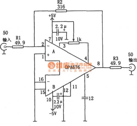
Wideband Video Amplifier Circuit with 50Ω Input/Output Impedance
Published:2011/5/17 6:28:00 Author:Joyce | Keyword: Wideband Video, Amplifier, with 50Ω Input/Output Impedance
 (View)
View full Circuit Diagram | Comments | Reading(740)
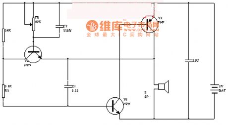
Utility Voice Control Electronic Doorbell Circuit
Published:2011/5/17 6:31:00 Author:Joyce | Keyword: Utility , Voice Control , Electronic , Doorbell
View full Circuit Diagram | Comments | Reading(708)
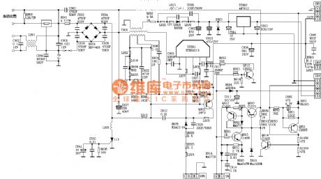
Panasonic L15 Circuit
Published:2011/5/17 6:32:00 Author:Joyce | Keyword: Panasonic , L15
View full Circuit Diagram | Comments | Reading(746)
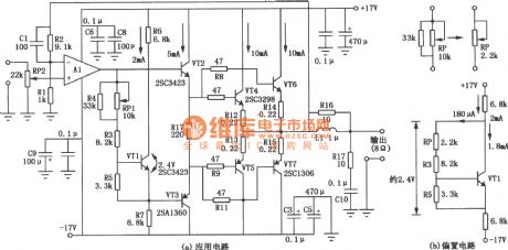
10W Power Amplifier Circuit
Published:2011/5/17 7:43:00 Author:Joyce | Keyword: 10W Power , Amplifier
 (View)
View full Circuit Diagram | Comments | Reading(912)
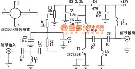
UHF Amplifier Circuit
Published:2011/5/17 6:08:00 Author:Joyce | Keyword: UHF, Amplifier
(View)
View full Circuit Diagram | Comments | Reading(3454)
Operational Amplifier Voltage Line Circuit
Published:2011/5/17 8:31:00 Author:Robert | Keyword: Operational Amplifier, Voltage, Line

The Operational Amplifier Voltage Line Circuit is shown below.
(View)
View full Circuit Diagram | Comments | Reading(655)
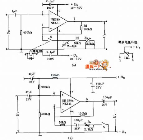
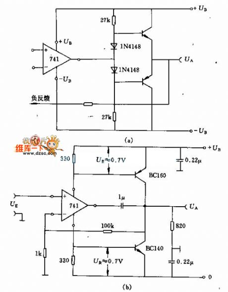
Wideband Amplifier Circuit
Published:2011/5/17 7:21:00 Author:Robert | Keyword: Wideband, Amplifier
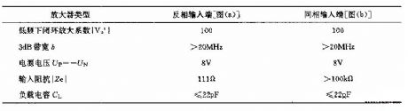
The Wideband Amplifier Circuit is shown below. The picture (a) and picture (b) have not only the differences on the input signal's symbol, but also the differences on the input impedance |Ze|. Its main technical data is listed below.
Amplifier TypeOut-phase input port (picture a) In-phase input port (picture b)
Low frequency closed-loop amplification factor |Vo'| 100 100
3dB bandwidth b >20MHz >20MHz
Supply Voltage Up=-Un 8V 8V
Input impedance |Ze| 111Ω >100kΩ
Load Capacitance Cl <=22pF <=22pF
(View)
View full Circuit Diagram | Comments | Reading(568)
Wideband Operational Amplifier Circuit
Published:2011/5/17 7:10:00 Author:Robert | Keyword: Wideband, Operational Amplifier
The Wideband Operational Amplifier Circuit is shown below.
(View)
View full Circuit Diagram | Comments | Reading(829)
Electric E Amplification Circuit
Published:2011/5/17 6:53:00 Author:Robert | Keyword: Electric E, Amplification
The Electric E Amplification Circuit is shown below.
(View)
View full Circuit Diagram | Comments | Reading(514)
AD574A interface circuit
Published:2011/5/16 7:55:00 Author:Christina | Keyword: interface circuit
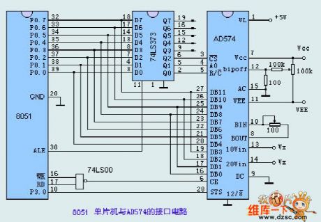
The 8051 single chip device and the AD574A's interface circuit is as shown, this circuit uses the three-state latcher 74LS373 and 74LS00 NAND gate circuit, the logic control signal is output by the 8051's data port, and latches to the output ports Q0, Q1 and Q2 by three-state latcher 74LS373 to control the working process of the AD574A.
Figure. AD574A interface circuit
AD converter's output data connects to the 8051 by P0 data bus, because we only use the 8-bit data port, so the 12-bit data reads into 8051 twice, so we connect it to the ground. When 8051's p3.0 inquires the STS port conversion end signal, the circuit will read the 12-bit A/D data's high 8-bit into 8051 first, then the low 4-bit. (View)
View full Circuit Diagram | Comments | Reading(2665)
Operational Amplifier Power Output Circuit
Published:2011/5/17 8:41:00 Author:Robert | Keyword: Operational Amplifier, Power Output
The Operational Amplifier Power Output Circuit is shown below.
(View)
View full Circuit Diagram | Comments | Reading(824)
Detection 4 ~ 20mA loop instrument amplifier (ISO120,XTR101)circuit diagram
Published:2011/5/16 20:43:00 Author:Ecco | Keyword: Detection , 4mA, 20mA, loop instrument , amplifier
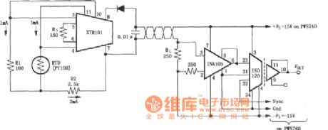
The RTDs isolated detection 4 ~ 20mA loop instrument amplifier circuit composed of ISO120 and INA105, XTR101 instrumentation amplifier is shown as the chart. Resistance temperature detector (RTD) can test temperature changing, the temperature changing can be changed into electrical signals which is input current loop amplifier XTR101, XTR101 transforms it into the 4 ~ 20mA current output, and the 4 ~ 20mA current is changed into voltage signal on the resistor RL by the twisted pair wires passing, and then amplified by the INA105 and sent to the isolation amplifier ISO120, and then it is isolated, amplified and output by ISO120. The main feature of the circuit is that the circuit uses XTR101 to transforme the input into 4 ~ 20mA current, the current signal can be transmitted in long distance, and it is not easy to get interference.
(View)
View full Circuit Diagram | Comments | Reading(1960)
Testing 4 ~ 20mA loop equipment amplifier (ISO122P/124, XTR101, RCV420) circuit diagram
Published:2011/5/17 2:33:00 Author:Ecco | Keyword: testing, 4 ~ 20mA, loop equipment , amplifier
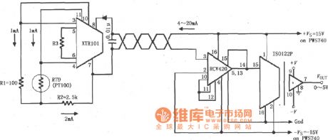
The RTDs isolated detection 4 ~ 20mA loop instrument amplifier circuit composed of ISO122P/124 and loop current transmission circuit XTR101, the loop current receiver circuit CV420 is shown as the chart. Resistance temperature detector (RTD) can test temperature changing, the temperature changing can be transformed into electrical signals input by XTR101, and then it is changed into the 4 ~ 20mA current output by XTR101, and then it transfered by the twisted pair and received by RCV420 , then the 4 ~ 20mA current is changed into voltage signal, the voltage signal is amplified and sent to isolation amplifier ISO122P, amplified, isolated by the ISO122P and it outputs 0 ~ 5V voltage.
(View)
View full Circuit Diagram | Comments | Reading(2101)
EGC right leg drive amplifier circuit diagram with defibrillator shock protection and calibrator
Published:2011/5/17 3:00:00 Author:Ecco | Keyword: EGC, right leg , drive amplifier , defibrillator shock protection , calibrator
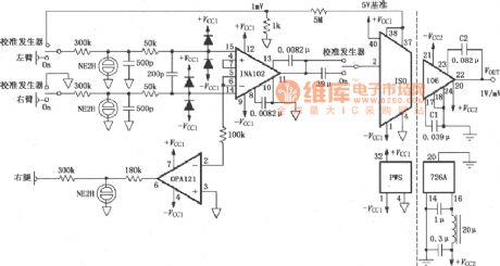
EGC right leg drive amplifier circuit with defibrillator shock protection and calibrator composed of INA102 and ISO106 is shown as the chart. The circuit has three ganged SPDT switches, the switch being connected to the calibration shows calibration state, the on shows the circuit being in measured state. When the circuit is in the measurement state, the output signal of left and right arm is amplified by INA102 and sent to the ISO106, and it is isolated, amplified and output by by ISO106. The output signal of of op amp OPA121 is the drive signal of right leg. When the circuit is in the calibration state, 5V reference voltage is divided by 5MΩ and 1kΩ resistors, it attenuates 5000 times.
(View)
View full Circuit Diagram | Comments | Reading(4070)
MAX4188/4189/4190 current-feedback amplifier circuit diagram with high-speed banned mode
Published:2011/5/17 3:09:00 Author:Ecco | Keyword: current-feedback , amplifier, high-speed , banned mode
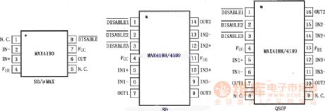
MAX4188/4189/4190 low-power current feedback amplifier has the low conversion transient state and high-speed enable / disable time. Three pieces of MAX4188 and single MAX4190 have closed-loop gain with +2 (6dB) or greater compensation to provide 200MHz-3dB bandwidth and 185MHz bandwidth respectively. Three pieces of MAX4189has closed-loop gain with +1 (0dB) or greater compensation to provide 250MHz-3dB bandwidth. The 0.1dB gain flatness of these amplifiers can reach 80MHz, differential gain is 0.03% and phase error is 0.055, all of these features make it be an ideal choice for video applications.
(View)
View full Circuit Diagram | Comments | Reading(508)
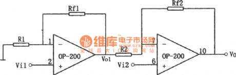
High input impedance in-phase differential amplifier circuit composed of OP200
Published:2011/5/16 10:02:00 Author:Rebekka | Keyword: High input impedance, in-phase differential amplifier
(View)
View full Circuit Diagram | Comments | Reading(614)
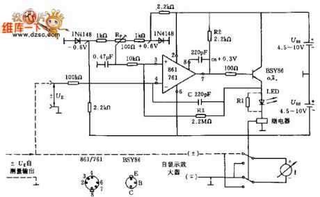
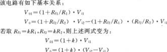
Automatic zeroing amplifier circuit composed of OPA2111BM
Published:2011/5/16 9:52:00 Author:Rebekka | Keyword: Automatic zeroing amplifier
Automatic zeroing amplifier circuit is shown as above. OPA2111 low bias (≤ ± 4pA), its setting up time is very short (1μs established to 0.01% accuracy), the noise is very small (8nV / (Hz) 1 / 2, 10kHz). It passes the automatic zeroing set can keep the offset voltage less than 5μV. Zero drift ≤ 0.028μV / C, converting to the input terminal and the zero potential regulation rate is ≤ 2μV / s. If you appropriately reduce the integration capacitor C, the zero potential adjusting speed can be improved. The voltage amplification factor is Av =- RF/R1 =- 100. (View)
View full Circuit Diagram | Comments | Reading(701)
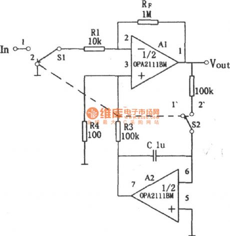
ISO100 optocoupler linear isolated amplifier circuit diagram
Published:2011/5/17 2:51:00 Author:Ecco | Keyword: optocoupler , linear , isolated amplifier
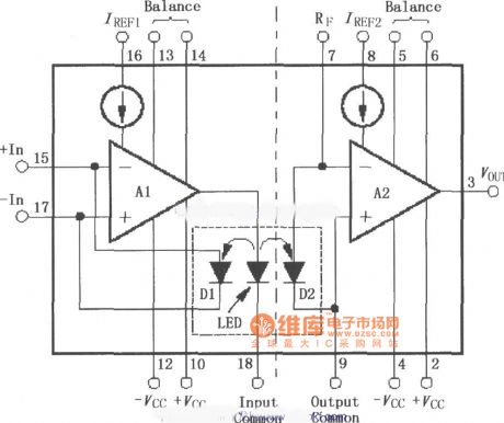
ISO100 is the optocoupler isolation amplifier. It uses LED to produce coupling light, and the negative feedback of coupling light is added to the input end, while the measures on output end of forward transmission can achieve a high precision, linear and long temperature stability. The fine matching coupler and amplifier laser correction ensure the integration of its excellent adjustment performance and low offset error. ISO100 can be used as a current - voltage converter, there is 750V (2500V test voltage) voltage between the input and output ends, it effectively disconnects the the contact of the public current between input and output ends with ultra-low leakage current, the maximum leakage current is 0.3μA when the current is at 240V, 60Hz.
(View)
View full Circuit Diagram | Comments | Reading(2577)
| Pages:219/250 At 20201202203204205206207208209210211212213214215216217218219220Under 20 |
Circuit Categories
power supply circuit
Amplifier Circuit
Basic Circuit
LED and Light Circuit
Sensor Circuit
Signal Processing
Electrical Equipment Circuit
Control Circuit
Remote Control Circuit
A/D-D/A Converter Circuit
Audio Circuit
Measuring and Test Circuit
Communication Circuit
Computer-Related Circuit
555 Circuit
Automotive Circuit
Repairing Circuit