
Index 202
The absolutely available switch power supply: Hitachi A1PM8C power supply
Published:2011/6/10 1:14:00 Author:Seven | Keyword: power supply, power supply
Oscillating process:After full-wave rectification, the 220V AC voltage is converted into a DC voltage of 300V on C906, and then the voltage is imposed on 3-pin of IC901 after it has run through the L1 coil of T901, in the meantime, the 220V is being half-wave rectified, then it is added to the 2-pin of IC901 by R942, R903 and R904, and the internal switch pipe of IC901 is starting to be conducting, besides, the current in L1 of T901 is rising, a positive feedback voltage in sensed in the coil L2, and this voltage is imposed on the 2-pin of IC901 by Q901, D905 and L907, so that the internal switch of IC901 is saturating quickly.During the time of saturating, on the one hand, L2 coil is charging C905 by R906 and R907. (View)
View full Circuit Diagram | Comments | Reading(539)
The absolutely available switch power supply: Kaige 4C7108 power supply
Published:2011/6/10 1:15:00 Author:Seven | Keyword: power supply, Kaige
The 5-pin is the power supply pin of TDA8380. The external C530, which is linked by the 10-pin, and the internal circuit, they both form a sawtooth wave oscillator. 6-pin links with an external R522, and the set parameter current provides charging/discharging current of C530, so the oscillator frequency of TDA8380 is decided by R500 and C530, the frequency of this machine is 34KHZ. The forward/backward motivating current, which is output by 1-pin and 15-pin of TDA8380, is delivered to the B pole of switch pipe Q502, so that Q502 is in the working state. It's to stop Q502 quickly to use backward motivation. (View)
View full Circuit Diagram | Comments | Reading(572)
The absolutely available switch power supply: Jinxing D2902 power supply
Published:2011/6/10 1:15:00 Author:Seven | Keyword: power supply, Jinxing
The oscillating process of switch circuitsThe 9-pin of STR-S6708 the power supply lead, and only when 9-pin is normally supplying power, does the thick film work normally.The VD908 is directly rectified on 220V AC current, and then it is limited by R903 and R917, and filtered by C909. After that, it becomes a DC current of about 8V and is imposed on 9-pin of IC901, so IC901 starts to work, and the switch power supply begins oscillate. Though the energy of the voltage, which is rectified by VD908, is low and can't keep IC901 normally working, when the power supply starts to oscillate, the V2-pin of switch transformer T901 is launching a voltage. (View)
View full Circuit Diagram | Comments | Reading(534)
The absolutely available switch power supply: Jinxing C7458 power supply
Published:2011/6/10 1:16:00 Author:Seven | Keyword: power supply, Jinxing
C7428 power supply is designed with wide voltage, which can adapt to the grid voltage of 110v-245v, and it is like the Toshiba 2500XH.
The shift circuit of the gridTo adapt to the grid voltage of 110v-245v, the circuit is designed to be able to shift double rectification/bridge rectification. When the voltage is lower than 145v, it shifts into double rectification; when the voltage is higher than 145v, it shifts into the bridge rectification. After the voltage, which is input by the grid, is low-pass filtered, it is firstly rectified by V801 and V802 and C808 gets a recognizing voltage, then the voltage is imposed on the 2-pin and 5-pin of STR81145. (View)
View full Circuit Diagram | Comments | Reading(624)
The Samsung 75DFhe755DF display diagram
Published:2011/6/10 1:07:00 Author:Seven | Keyword: display diagram
View full Circuit Diagram | Comments | Reading(591)
The digital controlled constant flow source
Published:2011/6/10 1:04:00 Author:Seven | Keyword: constant flow source
This is a digital controlled constant flow source of battery charging, which is designed by me. D/A converter outputs a voltage to the same polarity of the downside, the current in the circuit is I=Uad, it is fixed with sampling resistance, and two PORTs are used to connect the + and - poles. The upside transporting circuitry is connected as a amplifier circuit of 1/4 times, which is used to test the voltage of the battery. In the figure, 3dd13 and 3dd15 are the adjusting pipes. Please give me some suggestions. (View)
View full Circuit Diagram | Comments | Reading(723)
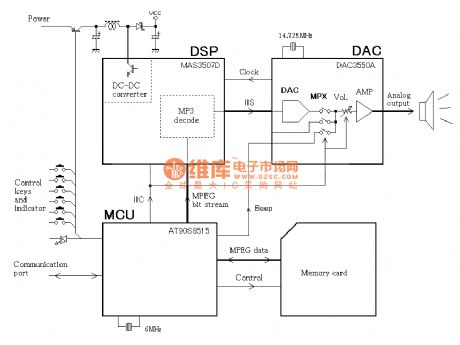
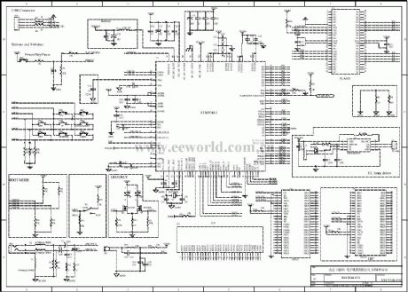
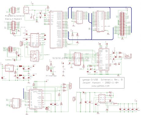
the hand-made MP3 player circuit and its data
Published:2011/6/10 1:18:00 Author:Seven | Keyword: hand-made, MP3 player
View full Circuit Diagram | Comments | Reading(1954)
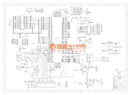
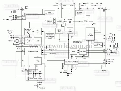
The radio circuit of the frequency LCD display (2)
Published:2011/6/10 1:08:00 Author:Seven | Keyword: radio circuit, frequency LCD display
View full Circuit Diagram | Comments | Reading(1510)
The chat transfer device of collinear phones (1)
Published:2011/6/10 1:04:00 Author:Seven | Keyword: chat transfer, collinear phones
View full Circuit Diagram | Comments | Reading(515)
The chat transfer device of collinear phones (2)
Published:2011/6/10 1:10:00 Author:Seven | Keyword: chat transfer, collinear phones
View full Circuit Diagram | Comments | Reading(559)
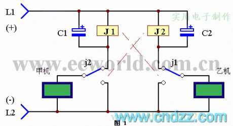
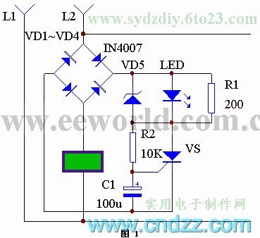
The circuit of a new type of electric mouse killer
Published:2011/6/10 1:27:00 Author:Seven | Keyword: electric mouse killer
It is said that mice are sensitive to magnetic field, which is why common high-voltage girds have bad effects on killing mice. The mice killer in the text has no high voltage ordinarily, so it won't cause the warning of mice, however, once mice touched the grid, the grid would generates a high voltage and kill the mice quickly. See as the figure, 1B is a separating and boost transformer. As the grid takes the earth as a pole, to prevent the mains protector from mistaking actions, the transformer is separated from the mains circuit. (View)
View full Circuit Diagram | Comments | Reading(927)
The portable phone wire distributor
Published:2011/6/10 1:19:00 Author:Seven | Keyword: phone wire, distributor
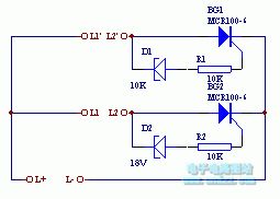
MCK100
(View)
View full Circuit Diagram | Comments | Reading(527)
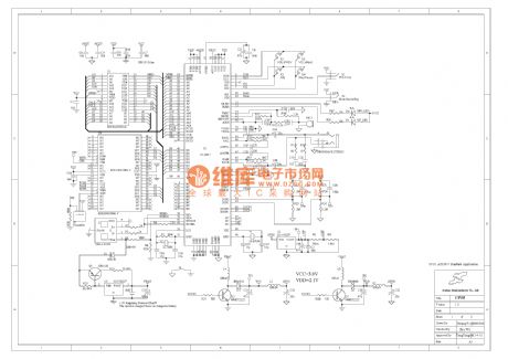
The principle diagram of IC reader/writer
Published:2011/6/10 1:11:00 Author:Seven | Keyword: principle diagram, IC reader/writer
This is a IC card and its reader/writer circuit, in which the reader/writer consists of a MPU, key board, display, supervision circuit and so on. The IC card is X76F100Y of XICOR.
2.1 the IC and its connectorX76F100 is a secure series FLASH E2PROM of 128*8 bit, of which either of the reader code and encoder code is 64 bit. The package pin of the smart card is as shown in Figure 2. The chip is packaged on a card, and the card is inserted into the connector of the IC reader, then the reader/writer and fulfills functions of encodeing, checking, saving,withdrawing and so on. (View)
View full Circuit Diagram | Comments | Reading(638)
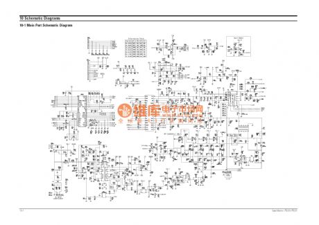
The MP3 hardware principle circuit (10)
Published:2011/6/10 1:12:00 Author:Seven | Keyword: hardware, principle circuit
View full Circuit Diagram | Comments | Reading(574)
The MP3 hardware principle circuit (09)
Published:2011/6/10 1:13:00 Author:Seven | Keyword: principle circuit
View full Circuit Diagram | Comments | Reading(573)
The MP3 hardware principle circuit (08)
Published:2011/6/10 1:20:00 Author:Seven | Keyword: principle circuit
View full Circuit Diagram | Comments | Reading(565)
The MP3 hardware principle circuit (06)
Published:2011/6/10 1:20:00 Author:Seven | Keyword: principle circuit
View full Circuit Diagram | Comments | Reading(584)
The MP3 hardware principle circuit (05)
Published:2011/6/10 1:22:00 Author:Seven | Keyword: MP3 hardware
View full Circuit Diagram | Comments | Reading(585)
the MP3 circuit(2)
Published:2011/6/10 1:22:00 Author:Seven | Keyword: MP3 circuit
View full Circuit Diagram | Comments | Reading(687)
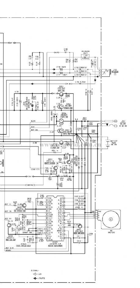
The Aiwa walkman hs-rx 108 circuit
Published:2011/6/10 1:26:00 Author:Seven | Keyword: Aiwa walkman
View full Circuit Diagram | Comments | Reading(1247)
| Pages:202/250 At 20201202203204205206207208209210211212213214215216217218219220Under 20 |
Circuit Categories
power supply circuit
Amplifier Circuit
Basic Circuit
LED and Light Circuit
Sensor Circuit
Signal Processing
Electrical Equipment Circuit
Control Circuit
Remote Control Circuit
A/D-D/A Converter Circuit
Audio Circuit
Measuring and Test Circuit
Communication Circuit
Computer-Related Circuit
555 Circuit
Automotive Circuit
Repairing Circuit