
Index 241
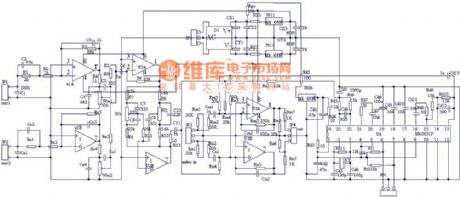
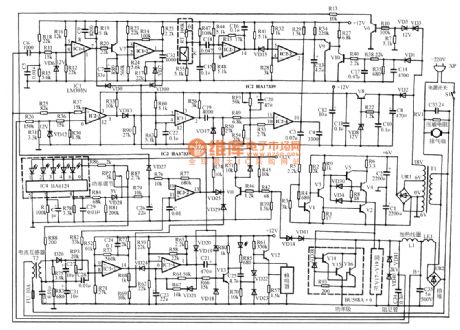
Kala OK delay reverberation M6583 circuit
Published:2011/4/15 2:19:00 Author:Jessie | Keyword: Kala OK, delay, reverberation
View full Circuit Diagram | Comments | Reading(1384)
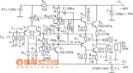
Rick McIntosh amplifier circuit
Published:2011/4/14 2:25:00 Author:Ecco | Keyword: Rick McIntosh

In the single-end push-pull circuit, for example, in Figure 23-8, a and C point are linked to be in low potential. But the earth point is not limited, any points on the coil a-b associating with the same potential point on the coil o-d can be used as earth point. In Figure 23-12, to connect the two mid-points of a-b, o-d to the earth, this is the basic form of Rick McIntosh amplifier circuit.
The two primary coils of the output transformer in circuit are directly related to the two primary coils of single-ended push-pull circuit, the everywhere's potential along the two potential coils is the same, so the primary coil is not influenced by electrostatic distributed capacitance, although they are two-lane around. This is one feature of Rick McIntosh amplifier circuit.
(View)
View full Circuit Diagram | Comments | Reading(525)
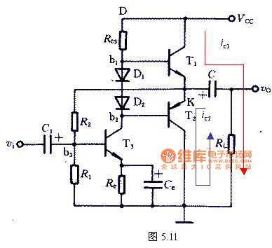
The basic form of two-stage amplifier voltage feedback circuit diagram
Published:2011/4/14 2:27:00 Author:Ecco | Keyword: basic form , voltage feedback , two-stage amplifier
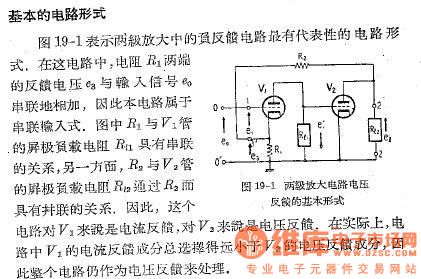
The basic form of circuit diagram
Figure 19-1 shows the most representative form of two-stage negative feedback amplifier circuit. In this circuit, the feedback voltage of the R1 connects to the input signal in series, so the circuit is in series input type. In the figure, the plate load impedances of R1 and V1 are series connected, on the other hand, the plate load impedances of R1 and V1 are parallel connected to R2. So the circuit is a current feedback circuit for V1, and a voltage feedback circuit for V2. In fact, the current feedback component of V1 is much smaller than the total voltage feedback component of V2, so the whole circuit is used as a voltage feedback circuit.
(View)
View full Circuit Diagram | Comments | Reading(815)
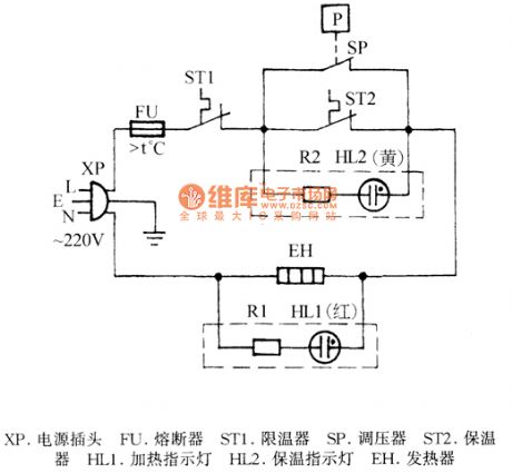
Feilu ZDY1-22 electric pressure cooker circuit
Published:2011/4/14 2:45:00 Author:Jessie | Keyword: electric pressure cooker

View full Circuit Diagram | Comments | Reading(784)
Dongming YB40A YB50A YB60A insulation automatic electric pressure cooker circuit
Published:2011/4/14 2:47:00 Author:Jessie | Keyword: insulation, automatic, electric pressure cooker
View full Circuit Diagram | Comments | Reading(1047)
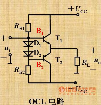
OCL Basic amplifying circuit 1
Published:2011/4/14 2:49:00 Author:Jessie | Keyword: OCL, amplifying
View full Circuit Diagram | Comments | Reading(594)
ocl power amplifying circuit
Published:2011/4/14 2:50:00 Author:Jessie | Keyword: power amplifying
View full Circuit Diagram | Comments | Reading(643)
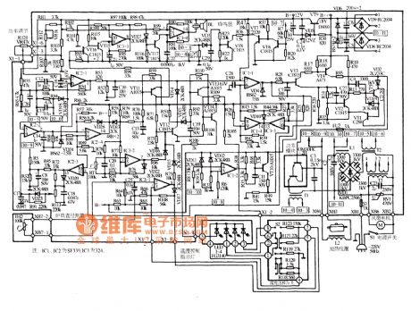
Yonghua ∑MO-88 induction cooker circuit
Published:2011/4/14 2:39:00 Author:Jessie | Keyword: induction cooker
View full Circuit Diagram | Comments | Reading(2785)
otl power amplifier circuit
Published:2011/4/14 2:40:00 Author:Jessie | Keyword: power amplifier
View full Circuit Diagram | Comments | Reading(858)
B amplification complementary symmetry circuit
Published:2011/4/14 2:41:00 Author:Jessie | Keyword: amplification, complementary symmetry
View full Circuit Diagram | Comments | Reading(486)
Suopu SP-220 induction cooker circuit
Published:2011/4/14 2:36:00 Author:Jessie | Keyword: induction cooker
View full Circuit Diagram | Comments | Reading(4673)
Supule SPL-10A induction cooker circuit
Published:2011/4/14 2:35:00 Author:Jessie | Keyword: induction cooker
View full Circuit Diagram | Comments | Reading(1514)
Orin induction cooker circuit
Published:2011/4/14 2:36:00 Author:Jessie | Keyword: induction cooker

View full Circuit Diagram | Comments | Reading(4184)
Haile DZC-1000W induction cooker circuit
Published:2011/4/14 2:16:00 Author:Jessie | Keyword: induction cooker
View full Circuit Diagram | Comments | Reading(2720)
Lily DZC-1 induction cooker circuit
Published:2011/4/14 2:28:00 Author:Jessie | Keyword: induction cooker
View full Circuit Diagram | Comments | Reading(965)
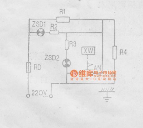
Sanzhanjiao CFXB Insulation automatic electric rice cooker circuit diagram
Published:2011/4/14 3:00:00 Author:Jessie | Keyword: Insulation, automatic, electric rice cooker
View full Circuit Diagram | Comments | Reading(1868)
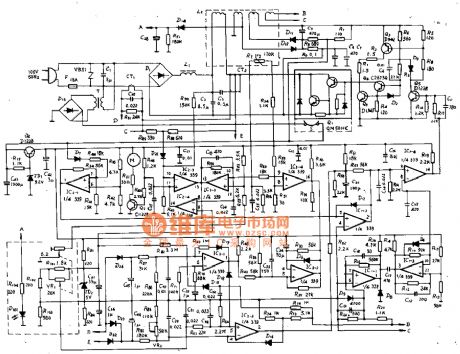
Sharp CY-103 induction cooker circuit
Published:2011/4/14 2:57:00 Author:Jessie | Keyword: induction cooker
View full Circuit Diagram | Comments | Reading(2218)
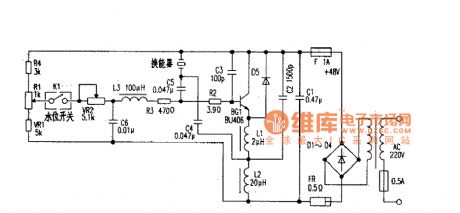
Ultrasonic humidifier overhaul circuit
Published:2011/4/14 2:56:00 Author:Jessie | Keyword: Ultrasonic humidifier, overhaul
View full Circuit Diagram | Comments | Reading(5494)
Massager circuit
Published:2011/4/14 3:04:00 Author:Jessie | Keyword: Massager


View full Circuit Diagram | Comments | Reading(923)
Photoelectric amplification circuit used in NC wire-cut machine
Published:2011/4/12 22:54:00 Author:Nicole | Keyword: NC wire-cut machine, photoelectric amplification
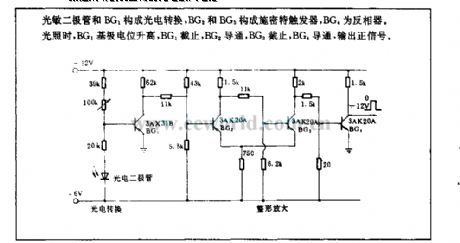
Photosensitive diode and BG1 form photoelectric conversion, BG2 and BG3 form Schmitt trigger, BG4 is inverter. When it is illumination, BG1 base potential rises, BG1 is off, then BG2 is conduction, BG2 is off, then BG4 is conduction, outputing positive singal. (View)
View full Circuit Diagram | Comments | Reading(591)
| Pages:241/250 At 20241242243244245246247248249250 |
Circuit Categories
power supply circuit
Amplifier Circuit
Basic Circuit
LED and Light Circuit
Sensor Circuit
Signal Processing
Electrical Equipment Circuit
Control Circuit
Remote Control Circuit
A/D-D/A Converter Circuit
Audio Circuit
Measuring and Test Circuit
Communication Circuit
Computer-Related Circuit
555 Circuit
Automotive Circuit
Repairing Circuit