
Index 243
SCM Buck-boost signal circuit diagram
Published:2011/4/11 3:44:00 Author:Rebekka | Keyword: SCM Buck-boost signal
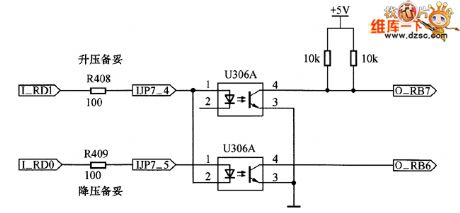
SCM Buck-boost signal circuit diagram is shown as below.
(View)
View full Circuit Diagram | Comments | Reading(578)
PIC16F73 and MAX485 interface circuit diagram
Published:2011/4/11 3:45:00 Author:Rebekka | Keyword: Interface circuit
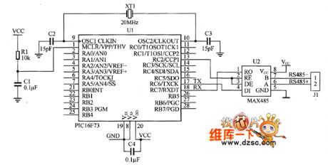
PIC16F73 and MAX485 interface circuit diagramis shown as below.
(View)
View full Circuit Diagram | Comments | Reading(12749)
MAX232 Interface circuit diagram
Published:2011/4/11 3:45:00 Author:Rebekka | Keyword: Interface circuit
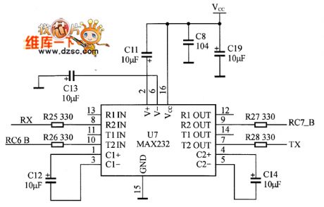
MAX232 Interface circuit diagramis shown as below.
(View)
View full Circuit Diagram | Comments | Reading(1971)
PDIUSBD12 and PlCl6F877 MCU interface circuit diagram
Published:2011/4/11 3:46:00 Author:Rebekka | Keyword: MCU interface circuit
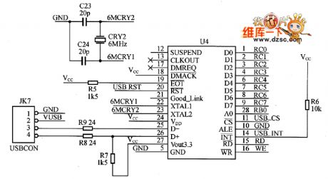
PDIUSBD12 and PlCl6F877 MCU interface circuit diagram is shown as below.
(View)
View full Circuit Diagram | Comments | Reading(4309)
PIC Microcontroller hardware interface circuit diagram
Published:2011/4/11 3:43:00 Author:Rebekka | Keyword: PIC Microcontroller, hardware interface
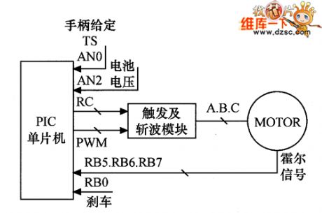
PIC Microcontroller hardware interface circuit diagram is shown as below.
(View)
View full Circuit Diagram | Comments | Reading(678)
HY8000A external small power audio amplifier circuit circuit
Published:2011/3/24 22:09:00 Author:may | Keyword: external small power audio amplifier
View full Circuit Diagram | Comments | Reading(455)
Adjustable volume RC coupled amplifier circuit
Published:2011/3/27 22:36:00 Author:may | Keyword: RC coupled amplifier circuit, Adjustable volume amplifier
Adjustable volume RC coupled amplifier circuit is shown in the diagram:
(View)
View full Circuit Diagram | Comments | Reading(1216)
OPA603 current feedback operational amplifier circuit
Published:2011/3/25 3:10:00 Author:may | Keyword: operational amplifier, current feedback operational amplifier
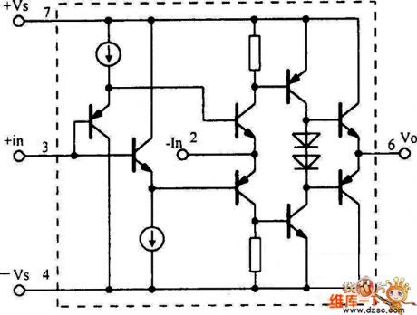
OPA603 current feedback operational amplifier circuit is shown in the following diagram:
(View)
View full Circuit Diagram | Comments | Reading(742)
Operational amplifier circuit diagram
Published:2011/4/7 3:04:00 Author:Ecco | Keyword: Operational amplifier
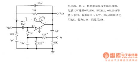
Single-supply, low voltage, low power operational amplifier circuit diagram.
IC operation can choose OPA2350, MAX412, OPA2344 and other low-voltage series. If the supply voltage of 5V, the resistor with* should use 42K, if it is 3.3V, use 27K.
(View)
View full Circuit Diagram | Comments | Reading(645)
Negative feedback superlinear amplifier circuit
Published:2011/4/7 22:22:00 Author:Ecco | Keyword: Negative feedback, superlinear amplifier
View full Circuit Diagram | Comments | Reading(743)
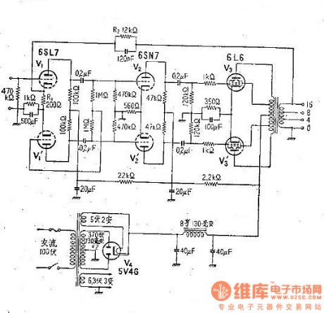
Williamson amplifier circuit diagram
Published:2011/4/7 22:23:00 Author:Ecco | Keyword: Williamson amplifier
View full Circuit Diagram | Comments | Reading(901)
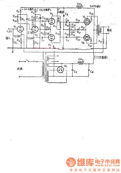
Amplifier circuit diagram (with negative feedback)
Published:2011/4/8 0:59:00 Author:Ecco | Keyword: Amplifier circuit , negative feedback
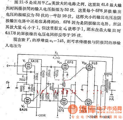
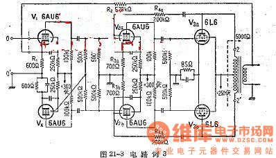
Figure 21-5 is an example of amplifier circuit using A,Ba. The maximum input voltage amplitude is 52V between two grids of 6L6. The output voltage of each 6F6 anode should be half of 52V, that is 28V, then the output voltage in cathode is easy to get. As 6F6 is cathode output circuit, the gain of a2 ' is less than 1. But if a2 ' is equal to 1, then the maximum output voltage 6AU6 is also equal to 26V. Now setting the gain a1 of V1 is equal to 145, you can find the net between the gate and the cathode input voltage. (View)
View full Circuit Diagram | Comments | Reading(1450)
The push-pull amplifier circuit diagram 3
Published:2011/4/8 1:07:00 Author:Ecco | Keyword: push-pull amplifier
View full Circuit Diagram | Comments | Reading(871)
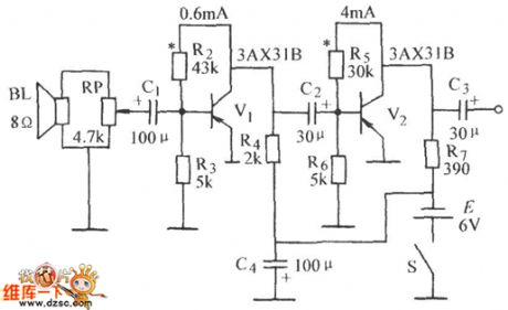
The push-pull amplifier circuit diagram 2
Published:2011/4/8 1:21:00 Author:Ecco | Keyword: push-pull amplifier
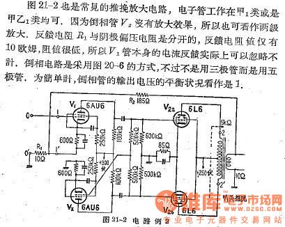
Figure 21-2 is a common push-pull amplifier circuit; And the tube can work in the class of A1 or AB1. As invert tube V2 has no amplification effect, it can be seen as polar amplification. Feedback resistor R1 is separate from the cathode bias resistor, the feedback resistance is only 10Ω, the resistance is very low, so the feedback current of V1 tube is negligible. Inverter circuit adopts the way of Figure 20-6, it does not use the transistor but use pentode, for simplicity, the balance of output voltage of the inverting tube is seen as 1.
(View)
View full Circuit Diagram | Comments | Reading(1103)
The push-pull amplifier circuit diagram 1
Published:2011/4/8 1:07:00 Author:Ecco | Keyword: push-pull amplifier
View full Circuit Diagram | Comments | Reading(754)
The amplifier circuit of electronic tube 6L6
Published:2011/4/8 2:15:00 Author:Ecco | Keyword: amplifier circuit , electronic tube

View full Circuit Diagram | Comments | Reading(1051)
Multi-level negative feedback circuit
Published:2011/4/8 2:13:00 Author:Ecco | Keyword: Multi-level, negative feedback
View full Circuit Diagram | Comments | Reading(613)
Amplifier lamp exposure circuit
Published:2011/4/7 20:32:00 Author:Nicole | Keyword: amplifier lamp, exposure
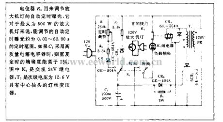
Potentiometer R1 is used to adjust automatic timing exposure of amplifier lamp, to this amplifier lamp which has 500W maximum power, the adjustable automatic timing exposure is about 0.01~60.00s. If C1 adopts high quality electrolytic capacitor, then the accuracy of repetition timing is higher than 2%. In figure, K1 is 24V AC relay, T1 is filament transformer with center tapped, and it has 12.6V secondary voltage. (View)
View full Circuit Diagram | Comments | Reading(619)
Amplifier lamp adjustment circuit
Published:2011/4/7 21:01:00 Author:Nicole | Keyword: amplifier lamp, adjustment
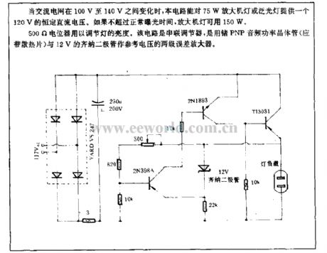
When AC network is changing between 100V~140V, this circuit can provide 75W amplifier lamp or flood light with a 120V DC constant voltage. If it has not beyond the normal exposure time, then 150W is available.
500Ω potentiometer is used to adjust the lamp brightness. This circuit is series regulator, and it is a two-stage error amplifier composed of germanium PNP audio power transistor(should with radiator)and 12V zener diode used as reference voltage. (View)
View full Circuit Diagram | Comments | Reading(1133)
Single-tuned amplifier circuit
Published:2011/3/28 22:33:00 Author:may | Keyword: Single-tuned amplifier
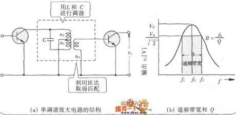
Single-tuned amplifier circuit is shown in the diagram:
(View)
View full Circuit Diagram | Comments | Reading(1741)
| Pages:243/250 At 20241242243244245246247248249250 |
Circuit Categories
power supply circuit
Amplifier Circuit
Basic Circuit
LED and Light Circuit
Sensor Circuit
Signal Processing
Electrical Equipment Circuit
Control Circuit
Remote Control Circuit
A/D-D/A Converter Circuit
Audio Circuit
Measuring and Test Circuit
Communication Circuit
Computer-Related Circuit
555 Circuit
Automotive Circuit
Repairing Circuit