
Speaker
Index
Wiring Circuit of the Speaker
Published:2011/9/12 23:55:00 Author:Zoey | Keyword: Wiring Circuit, Speaker
Picture 20 shows the connection cable of the speaker, the connection cable uses a resistance that has small consumption and good response. Generally, speakers’ resistance is about several Ωto dozens Ω,and it is largely affected by power pinchoff produced by cable equivalent resistance. Therefore, the cable chose should have a low current resistance. In addition, frequency response of transportation signal is mainly determined by texture and material of the cable, the cable should be easily controlled by frequency response.
How to choose transistors and FET
Transistor circuits can be mainly divided into amplified circuit, switched circuit and oscillation circuit. Transistors available for these circuits are high frequency transistors, high amplifier factor transistors, high power transistors and general transistors.
General transistors: Japanese 2SA1048(UCEO=50V,Ic=150MA,Pc=200mW,hFE=70~400,T=80MHZ) and 2SC245(UCEO=5OV,Ic=15OMA,PC=2OOmW,hFE=70~700,T=80MHZ);Genral high frequency transitors: Japanese 2SC2668(UcEO=30V,Ic=2OmA,Pc=1OOmW,hFE=40~200,T=550MHZ) and 2SC3136(UCEO=20V,Ic=50mA,PC=250mW,hfe=40~300,T=1400KHZ);Genral crystal transitors: Japanese 2SA1516(UcEO=180V,IC=12A,Pc=130W,hFE=55~180,T=25MHZ) and 2SC3907(UCEO=180V,Ic=12A,PC=130W,hFE=55~180,T=30MHZ);
Genral dual transitors:Japanese 2SA1349(UCEO=80V,Ic=100MA,Pc=200mWx2,hFE=200~700)and 2SC3381(VCEO=80V,IC=1OOMA,Pc=200x2mW,hFE=200~700)。Chinese low power low frequency transistors:3AX、3BX、3CX、3DX series. General FET:2SJ105(UGDS=5OV,IDSS=1.2~1.4mA,PD=2OOmW,Ciss=18pF) and 2SK330(UGDS=5OV,IDSS=1.2~1.4mA,PD=2OOmW,CISS=9pF);High frequency FET:2SK241(UGDS=2OV,IDSS=1.5~14mA,PD=2OOmW,Ciss=3pF);Power FET: 2SJ200(UGDS=180V,IDSS=1OA,PD=12OW,CiSS=1300pF) and 2SK1529(UGDS=180V,IDSS=1OA,PD=12OW,Cis=700pF);Dual tubes:2SJ109(UGDS=30V,IDSS=2.6~2OmA,PD=2OOmW,Ciss=95pF) and 2SK389(UGDS=5OV,IDSS=2.6~2OmA,PD=2OOmW,Ciss=25pF)。 (View)
View full Circuit Diagram | Comments | Reading(1644)
HIGH_IMPEDANCE_MICROPHONE_INPUT_CIRCUIT
Published:2009/6/18 23:56:00 Author:May
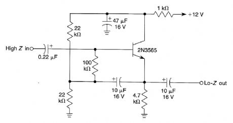
This input circuit will enable use of a high-impedance microphone where a low-impedance microphone would be needed. (View)
View full Circuit Diagram | Comments | Reading(1414)
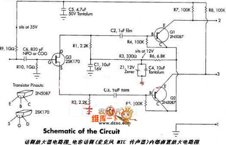
Microphone amplifier circuit diagram 1
Published:2011/3/25 1:48:00 Author:Ecco | Keyword: Microphone amplifier
Microphone amplifier circuit diagram 1 is as below:
(View)
View full Circuit Diagram | Comments | Reading(955)
Microphone amplifier circuit diagram 2
Published:2011/3/25 1:49:00 Author:Ecco | Keyword: Microphone amplifier
View full Circuit Diagram | Comments | Reading(1111)
Circuit Categories
power supply circuit
Amplifier Circuit
Basic Circuit
LED and Light Circuit
Sensor Circuit
Signal Processing
Electrical Equipment Circuit
Control Circuit
Remote Control Circuit
A/D-D/A Converter Circuit
Audio Circuit
Measuring and Test Circuit
Communication Circuit
Computer-Related Circuit
555 Circuit
Automotive Circuit
Repairing Circuit