
Index 468
The internal circuit diagram of crystal diode IMH23、IMH3A、IMH4A
Published:2011/3/29 1:23:00 Author:Ecco | Keyword: crystal diode
The internal circuit diagram of crystal diode IMH23、IMH3A、IMH4A is as below:
(View)
View full Circuit Diagram | Comments | Reading(628)
150W UPS Circuit diagram
Published:2011/3/22 22:40:00 Author:Rebekka | Keyword: 150W UPS
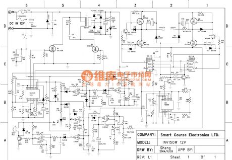
150W UPS Circuit diagram is shown as below.
(View)
View full Circuit Diagram | Comments | Reading(13836)
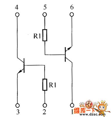
Crystal triode IMH1A、IMH2A、IMH9A inside circuit diagram
Published:2011/3/24 0:57:00 Author:Ecco | Keyword: Crystal triode
Crystal triode IMH1A、IMH2A、IMH9A inside circuit diagram is as below:
(View)
View full Circuit Diagram | Comments | Reading(536)
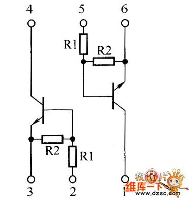
Crystal triode IMH5A、IMH6A inside circuit diagram
Published:2011/3/20 22:56:00 Author:Ecco | Keyword: Crystal triode
Crystal triode IMH5A、IMH6A inside circuit diagram is as below:
(View)
View full Circuit Diagram | Comments | Reading(480)
Venturi Filter circuit diagram
Published:2011/3/20 22:56:00 Author:Ecco | Keyword: Venturi Filter
Venturi Filter circuit diagram is as below:
(View)
View full Circuit Diagram | Comments | Reading(669)
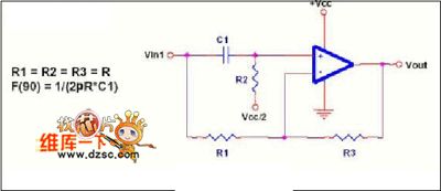
Resonator grid drive circuit diagram
Published:2011/3/28 3:57:00 Author:Nicole | Keyword: Resonator grid
View full Circuit Diagram | Comments | Reading(604)
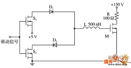
Serial electronic rectifier circuit diagram
Published:2011/3/28 4:03:00 Author:Nicole | Keyword: electronic rectifier
View full Circuit Diagram | Comments | Reading(513)
Sourcefree buzzer drive circuit diagram
Published:2011/3/20 22:55:00 Author:Ecco | Keyword: Sourcefree buzzer, drive
Sourcefree buzzer drive circuit diagram is as below:
(View)
View full Circuit Diagram | Comments | Reading(559)
ATS anti-thief system circuit diagram
Published:2011/3/20 22:53:00 Author:Ecco | Keyword: ATS anti-thief system
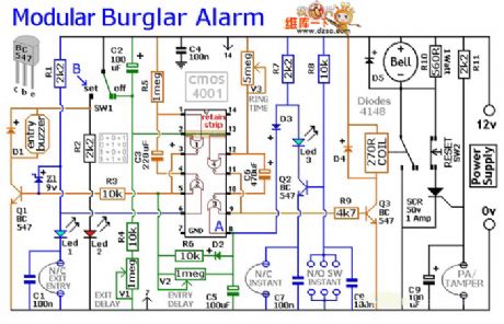
ATS anti-thief system circuit diagram is as below:
(View)
View full Circuit Diagram | Comments | Reading(3935)
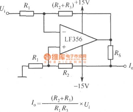
Constant current source circuit with adjustable output current
Published:2011/3/25 0:38:00 Author:Joan | Keyword: Constant current source , adjustable output current , three-terminal fixed output , integrated voltage regulator
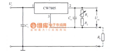
Above is Constant current source circuit with adjustable output current consisted of three-terminal fixed output integrated voltage regulator. (View)
View full Circuit Diagram | Comments | Reading(812)
The inside circuit diagram of crystal triode MFJ6668
Published:2011/3/20 22:51:00 Author:Ecco | Keyword: crystal triode
The inside circuit diagram of crystal triode MFJ6668 is as below:
(View)
View full Circuit Diagram | Comments | Reading(558)
Driving buzzer circuit diagram in power driving level
Published:2011/3/29 1:52:00 Author:Ecco | Keyword: Driving buzzer, power driving level
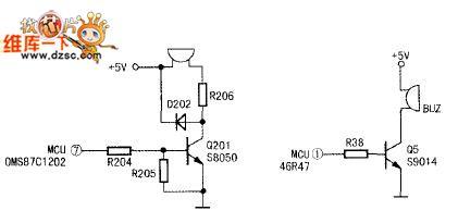
Driving buzzer circuit diagram in power driving level is as below:
(View)
View full Circuit Diagram | Comments | Reading(2790)
LED display circuit diagram driving by 74HC595
Published:2011/3/28 22:11:00 Author:Ecco | Keyword: LED display
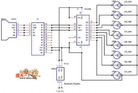
LED display circuit diagram driving by 74HC595 is as below:
(View)
View full Circuit Diagram | Comments | Reading(4163)
Digital set type standard power supply circuit(CD4516, μA723C)diagram
Published:2011/3/22 21:55:00 Author:Rebekka | Keyword: Digital set type, standard power supply
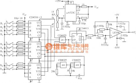
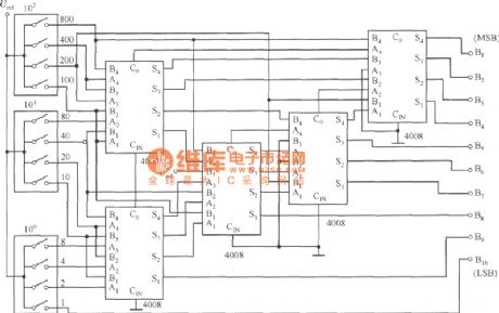
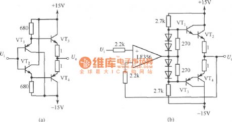
Digital set type standard power supply circuit diagram is shown as below. It is composed of digital set voltage switch(S1~S10), digital set type PWM circuit(CD4516, CD4025 and CD4013), smoothing PWM signal filter(LF356), clock generator(CD4025) and reference voltage source. Output voltage is set by Sl~S10, setting code is binary code. RPl is used for full-scale adjustment. Output voltage Uo will be adjusted to 10.23V when the digital input are all l. Filter gains 2 times(6dB), therefore, Uref is the half of 10.23V, voltage setting step is 10mV. To use the BCD-Binary number conversion circuit figure shown below when you use digital switch BCD code to set voltage. At this time, Uo is set to 3-digit display. The output voltage is 9.99V when the step voltage is 10mV.
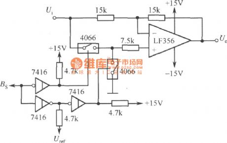
If you want to convert the polarity of output voltage, you can use the circuit diagram shown as below. The output Uo is positive voltage when Bs is 0; The output Uo is negative voltage when Bs is l. If you want to increase output power, you can use PA shown as the figure. But ±l5V power supply needs enough output power. If you want to change standard voltage into standard current source, you can add constant current circuit shown as the figure.
Output positive and negative voltage polarity converting circuit diagram:
PA circuit diagram:
Constant current circuit disgram:
(View)
View full Circuit Diagram | Comments | Reading(3253)
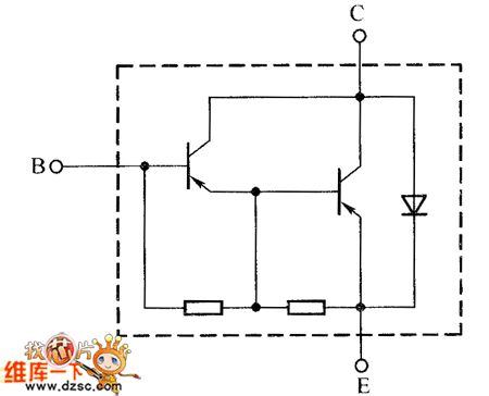
The inside circuit diagram of MMBT6427LT1 crystal triode
Published:2011/3/20 22:52:00 Author:Ecco | Keyword: MMBT6427LT1 crystal triode
The inside circuit diagram of MMBT6427LT1 crystal triode is as below:
(View)
View full Circuit Diagram | Comments | Reading(522)
The inside circuit diagram of crystal triode NUS2401SNT1
Published:2011/3/22 1:13:00 Author:Ecco | Keyword: crystal triode
The inside circuit diagram of crystal triode NUS2401SNT1 is as below:
(View)
View full Circuit Diagram | Comments | Reading(482)
The white LED drive circuit diagram with TL499A
Published:2011/3/24 21:59:00 Author:Ecco | Keyword: white LED drive
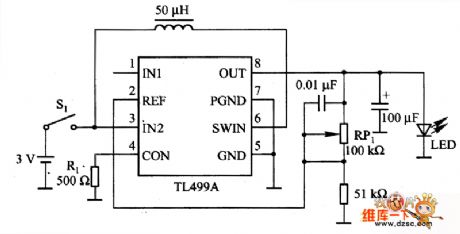
Here is the chart of the white LED drive circuit diagram with TL499A. The voltage of white LED drives is about 3.6V. If supplied common battery, it needs boosting circuitry composing of TL499A. TL499A is a type of adjustable output voltage integrated voltage regulation, and switching (voltage) regulator and linear regulator type can change automaticly when rising in switching (voltage) regulator type and descending in linear regulator type. The input voltage has a wide range of 1·1一10V(the switch works), the maximum is 35V(linear regulator works); the output voltage has a wide range of 2·9一30V, the maximum current is 100mA. In the chart, the working supplied by 2 sections of batteries in series connection, the crest value of switching current Ip of TL449A's pin 4 is about 200mA when R1 is -500 Ω. The resistance is low while the output current is high, Ip will increase simultaneously. RP1 is used as adjusting the output voltage. (View)
View full Circuit Diagram | Comments | Reading(2058)
The inside circuit diagram of PEMD10 crystal triode
Published:2011/3/20 22:52:00 Author:Ecco | Keyword: crystal triode
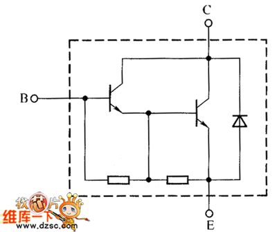
The inside circuit diagram of PEMD10 crystal triode is as below:
(View)
View full Circuit Diagram | Comments | Reading(496)
Beelink tumbling-type massor circuit diagram
Published:2011/3/20 22:51:00 Author:Ecco | Keyword: tumbling-type massor
Beelink tumbling-type massor circuit diagram is as below:
(View)
View full Circuit Diagram | Comments | Reading(549)
LED display circuit diagram driving by 74HC164
Published:2011/3/28 22:10:00 Author:Ecco | Keyword: LED display
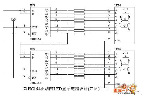
LED display circuit diagram driving by 74HC164 is as below:
(View)
View full Circuit Diagram | Comments | Reading(7486)
| Pages:468/471 At 20461462463464465466467468469470471 |
Circuit Categories
power supply circuit
Amplifier Circuit
Basic Circuit
LED and Light Circuit
Sensor Circuit
Signal Processing
Electrical Equipment Circuit
Control Circuit
Remote Control Circuit
A/D-D/A Converter Circuit
Audio Circuit
Measuring and Test Circuit
Communication Circuit
Computer-Related Circuit
555 Circuit
Automotive Circuit
Repairing Circuit