
Index 336
ZERO_CENTER_INDICATOR_FOR_FM_RECEIVERS
Published:2009/6/24 21:26:00 Author:May
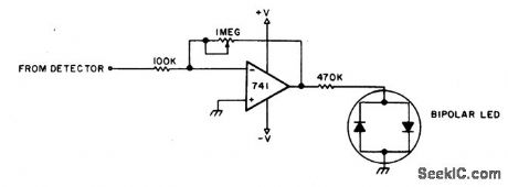
To adjust, tune in a station and adjust the 1 M pot for a null. Then ask the station to modulate and fine adjust so modulation peaks don't light the LEDs. Stations are properly tuned when neither LED is lit. (View)
View full Circuit Diagram | Comments | Reading(0)
FM_BUG
Published:2009/6/24 21:24:00 Author:May
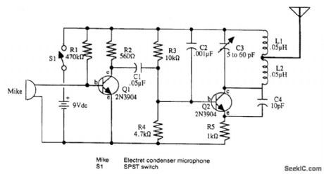
View full Circuit Diagram | Comments | Reading(693)
FM_STEREO_TRANSMITTER
Published:2009/6/24 21:21:00 Author:May
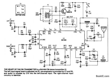
An FM stereo transmitter can be built around the BA1404 IC. This IC has all the functions necessary to generate an FM MPX signal. A separator oscillator circuit uses a 2N5210 transistor instead of the difficult-to-find 38-kHz crystal that is normally used. T1 is a 455-kHz IF transformer with 0.0039-μF capacitance added across it to enable tuning to 38 kHz. With this circuit, oscillator stabil-ity should be adequate. (View)
View full Circuit Diagram | Comments | Reading(0)
TEN_STEP_VOLTAGE_LEVEL_INDICATOR
Published:2009/6/24 21:21:00 Author:May
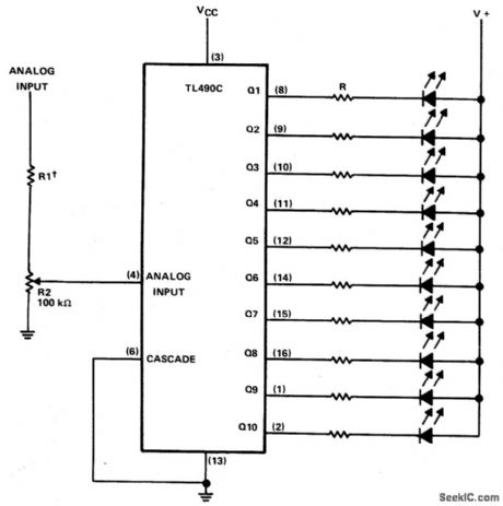
This ten-step adjustable analog level detector is capable of sinking up to 40 milliamperes at each output. The voltage range at the input pin should range from 0 to 2 volts. Circuits of this type are useful as liquid-level indicators, pressure indicators, and temperature tector dicators. They may also be used with a set of peres at active filters to provide a visual indication of input pin harmonic content of audio signals. (View)
View full Circuit Diagram | Comments | Reading(2500)
WIRELESS_MICROPHONE
Published:2009/6/24 21:20:00 Author:May
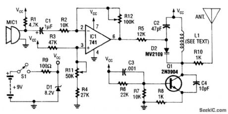
An op-amp IC (741) amplifies the audio signal from MIC1, and R12 controls its gain. Audio is fed to the oscillator circuit Q1 and related components. D2 is a varactor diode. Audio fed to D2 causes FM of the oscillator signal. L1 is 1/2 turns of #18 wire on a He diameter form. The antenna is a 12 whip. (View)
View full Circuit Diagram | Comments | Reading(0)
WIRELESS_GUITAR_TRANSMITTER
Published:2009/6/24 21:16:00 Author:May
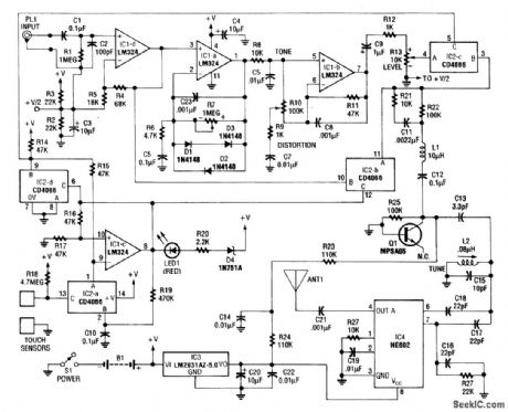
This transmitter has a built-in distortion effects unit and a touch switch to switch effects off and on. The circuit operates from a 9-V battery. IC1-a and IC1-b are used in the effects circuitry. IC1-d is an input preamp and IC2 is a quad analog switch to handle audio switching. Q1 acts as a varactor diode modulator while IC-4 is an 88- to 108-MHz FM oscillator. (View)
View full Circuit Diagram | Comments | Reading(0)
SIGNAL_TRACER
Published:2009/6/24 21:13:00 Author:May
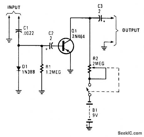
This circuit uses a simple detector-audio am-plifier. The output can be connected to head-phones or another audio amplifier. (View)
View full Circuit Diagram | Comments | Reading(0)
CABLE_TRACER
Published:2009/6/24 21:12:00 Author:May
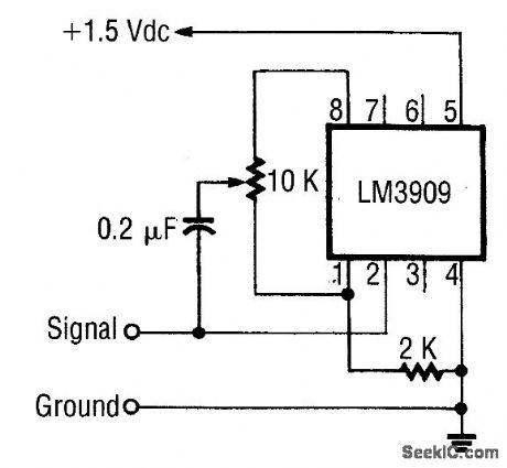
This circuit generates a 1-kHz square wave for cable tracing. Because this circuit is simple and generates from 1.5 V, several can be used at the same time to generate multiple tones for tracing multiconductor cables. (View)
View full Circuit Diagram | Comments | Reading(0)
WIRE_TRACER
Published:2009/6/24 21:12:00 Author:May

This tracer works by placing a square-wave signal on the line to be traced. The square wave is rich in harmonics. A small transistor radio placed close to a wire carrying this signal will buzz. The ra-dio, therefore, is used as a probe to trace out the wire. (View)
View full Circuit Diagram | Comments | Reading(0)
CAPACITIVE_SENSOR_SYSTEM
Published:2009/6/24 21:08:00 Author:May
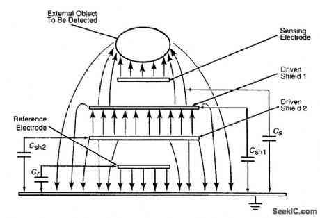
This figure illustrates the electric-field configuration of a capacitive proximity sensor of the ca-paciflector type. It includes a sensing electrode driven by an alternating voltage, which gives rise to an electric field in the vicinity of the electrode; an object that enters the electric field can be de-tected by its effect on the capacitance between the sensing electrode and electrical ground.Also, it includes a shielding electrode (in this case, driven shield 1), which is excited via a volt-age follower at the same voltage as that applied to the sensing electrode to concentrate more of the electric outward from the sensing electrode, increasing the sensitivity and range of the sensor. Be-cause the shielding electrode is driven via a voltage follower, it does not present a significant elec-trical load to the source of the alternating voltage.In this case, the layered electrode structure also includes a reference electrode adjacent to ground, plus a second shielding electrode (driven shield 2), which is excited via a voltage follower at the same voltage as that applied to the reference electrode. Driven shield 2 isolates the reference electrode from the electric field generated by driven shield 1 and the sensing electrode so that a nearby object exerts no ca[acitive effect on the reference electrode.The excitation is supplied by a crystal-controlled oscillator and applied to the sensing and ref-erence electrodes via a bridge circuit. Fixed capacitors C1 and C2 (or, alternatively, fixed resistors RI and R2) are chosen to balance the bridge; that is, to make the magnitude of the voltage at sens-ing-electrode node S equal the magnitude of the voltage at reference-electrode node R.The voltages at S and R are peak-detected and fed to a differential amplifier, which puts out volt-age 7, proportional to the difference between them. When no object intrudes into the electric field of the sensing electrode, the bridge remains in balance, and Vu - 0. When an object intrudes, it changes CS, unbalances the bridge, and causes Vu to differ from zero. The closer the object comes to the sensing electrode, the larger (Vu) becomes.An additional output voltage KVr is available, where K is the amplification and Vr is the voltage on the reference electrode. (View)
View full Circuit Diagram | Comments | Reading(0)
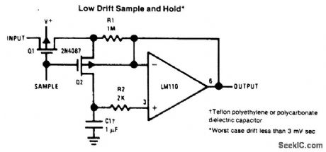
LOW_DRIFT_SAMPLE_AND_HOLD
Published:2009/6/24 20:59:00 Author:May
View full Circuit Diagram | Comments | Reading(0)
CRYSTAL_CHECKER
Published:2009/6/24 20:59:00 Author:May
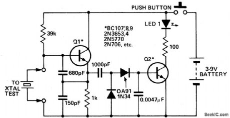
Use this circuit for checking fundamental HF crystals on a 'Go-No-Go' basis. An untuned Colpitts oscillator drives a voltage multiplier rectifier and a current amplifier. If the crystal oscillates, Q2 conducts and the LED lights. A3 or 6V, 40mA bulb could be substituted for the LED. (View)
View full Circuit Diagram | Comments | Reading(0)
MICROPOWER_4_CHANNEL_SAMPLE_AND_HOLD_CIRCUIT
Published:2009/6/24 20:59:00 Author:May
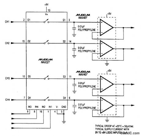
Three Maxim ICs make up this sample-and-hold circuit. The supply current is only 6μA. (View)
View full Circuit Diagram | Comments | Reading(0)
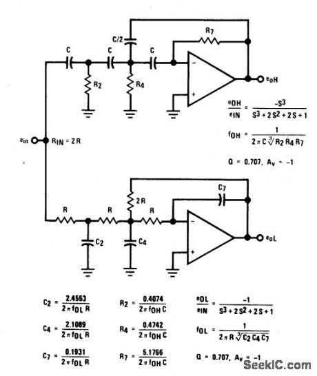
THIRD_ORDER_BUTTERWORTH_CROSSOVER_NETWORK
Published:2009/6/24 20:38:00 Author:May
View full Circuit Diagram | Comments | Reading(0)
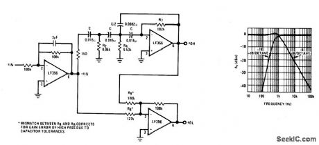
ASYMMETRICAL_THIRD_ORDER_BUTTERWORTH_ACTIVE_CROSSOVER_NETWORK
Published:2009/6/24 20:38:00 Author:May
View full Circuit Diagram | Comments | Reading(0)
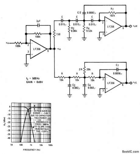
ACTIVE_CROSSOVER_NETWORK
Published:2009/6/24 20:36:00 Author:May
View full Circuit Diagram | Comments | Reading(0)
IONIZATION_CHAMBER_SMOKE_DETECTOR
Published:2009/6/24 21:15:00 Author:Jessie
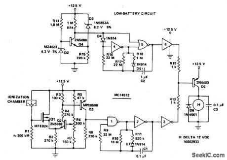
Battery-operated, ionization chamber smoke detector includes a circuit to generate a unique alarm when the battery reaches the end of its useful life. The circuit uses the MCMOS MC14572 for two alarm oscillators (smoke and low battery). This circuit additionally uses five discrete transistors as buffers and comparators. (View)
View full Circuit Diagram | Comments | Reading(2474)
FAST_TURN_ON_DELAYED_OFF_RELAY_CIRCUIT
Published:2009/6/24 5:41:00 Author:May
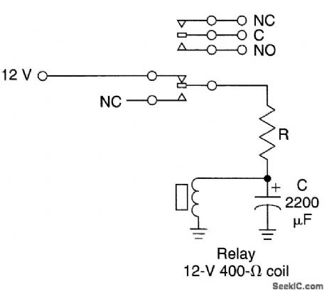
C is a large capacitor that has a charge time of RSUPPLY C, assuming RSUPPLY <Rcoil, The discharge time will be Rcoil C neglecting relay coil inductance. With C = 10,000 μF and Rcoil 500 Ω, a release time constant of 5 seconds might be obtained. Many relays will hold in until the coil current decays to 25% of the pull-in current so that the actual time constant depends on the relay holding current. (View)
View full Circuit Diagram | Comments | Reading(0)
ZERO_VOLTAGE_SWITCHING_TEMPERATURE_REGULATOR
Published:2009/6/24 4:32:00 Author:May

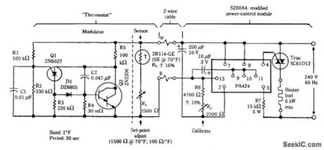
In this arrangement, an integral number of cycles of ac is fed to the heater. No RFI or EMI is gen-erated with this method. The thermostat uses a thermistor as a sensor. The PA424 (GE) device gen-erates trigger pulses for the triac only at zero crossings of the ac line cycle. (View)
View full Circuit Diagram | Comments | Reading(1504)
MICROPOWER_4_CHANNEL_SAMPLE_AND_HOLD_CIRCUIT
Published:2009/6/24 20:59:00 Author:Jessie
Three Maxim ICs make up this sample-and-hold circuit. The supply current is only 6μA. (View)
View full Circuit Diagram | Comments | Reading(1099)
| Pages:336/471 At 20321322323324325326327328329330331332333334335336337338339340Under 20 |
Circuit Categories
power supply circuit
Amplifier Circuit
Basic Circuit
LED and Light Circuit
Sensor Circuit
Signal Processing
Electrical Equipment Circuit
Control Circuit
Remote Control Circuit
A/D-D/A Converter Circuit
Audio Circuit
Measuring and Test Circuit
Communication Circuit
Computer-Related Circuit
555 Circuit
Automotive Circuit
Repairing Circuit