
Basic Circuit
Index 49
TOUCH SWITCH and TOUCH ON-OFF Circuit
Published:2013/3/5 20:55:00 Author:Ecco | Keyword: TOUCH SWITCH , TOUCH ON-OFF
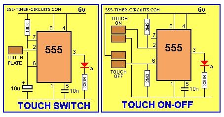
The Touch Switch circuit will detect stray voltages produced by mains voltages and electrostatic build-up in a room. In the first circuit, pin 2 must see a LOW for the circuit to activate. If sufficient static voltage is detected by the plate, the chip will change state. If not, you will need to touch the plate and the 0v rail. In the second circuit, two touch plates are provided and the resistance of your finger changes the voltage on pin 2 or 6 to toggle the 555.
(View)
View full Circuit Diagram | Comments | Reading(6748)
TILT SWITCH Circuit
Published:2013/3/5 20:53:00 Author:Ecco | Keyword: TILT SWITCH

The output is LOW at start-up due to the capacitor on pin 4. When the mercury switch closes, the output goes HIGH and remains HIGH until the reset button is pressed. This circuit is called a LATCH.
(View)
View full Circuit Diagram | Comments | Reading(1140)
STUN GUN Circuit
Published:2013/3/5 20:52:00 Author:Ecco | Keyword: STUN GUN
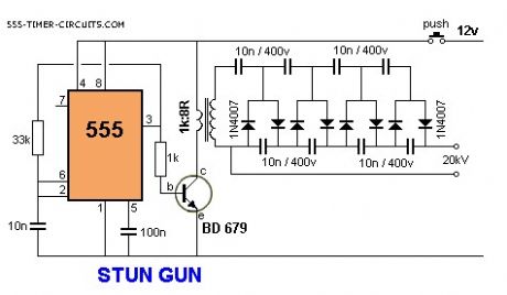
This circuit produces a very high voltage and care must be used to prevent getting a nasty shock.The transformer can produce over 1,000v and the 8-stage multiplier can produce up to 20,000v.
(View)
View full Circuit Diagram | Comments | Reading(4887)
SIREN 100dB Circuit
Published:2013/3/5 20:46:00 Author:Ecco | Keyword: SIREN 100dB
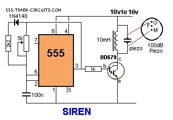
This is a very loud siren and if two or more piezo's are located in a room, the burglar does not know where the sound is coming from. A robber will not stay anywhere with an ear-piercing sound as he cannot hear if someone is approaching. It's the best deterrent you can get. The F contact on the piezo is feedback and is not needed in this circuit.
(View)
View full Circuit Diagram | Comments | Reading(1357)
POLICE SIREN Circuit
Published:2013/3/5 20:37:00 Author:Ecco | Keyword: POLICE SIREN
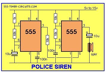
The Police Siren circuit uses two 555's to produce an up-down wailing sound. The first 555 is wired as a low-frequency oscillator to control the VOLTAGE CONTROL pin 5 of the second 555. The voltage shift on pin 5 causes the frequency of the second oscillator to rise and fall.
(View)
View full Circuit Diagram | Comments | Reading(1218)
MUSIC BOX Circuit
Published:2013/3/5 0:33:00 Author:Ecco | Keyword: MUSIC BOX
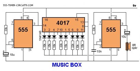
This circuit produces 10 different tones and by selecting suitable values to change the voltage on pin 5, the result can be quite pleasing. Note: the two unused outputs of the 4017 produce a tone equal to that produced by the 555 when pin 5 has no external control voltage.
(View)
View full Circuit Diagram | Comments | Reading(1773)
MOTOR PWM Circuit
Published:2013/3/5 0:32:00 Author:Ecco | Keyword: MOTOR PWM
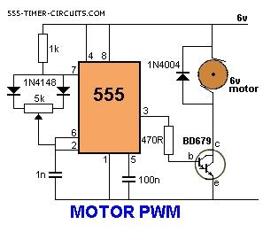
The speed of a motor can be adjusted by this circuit, from 5% to 95%.
(View)
View full Circuit Diagram | Comments | Reading(1098)
MOSQUITO REPELLER Circuit
Published:2013/3/5 0:31:00 Author:Ecco | Keyword: MOSQUITO REPELLER
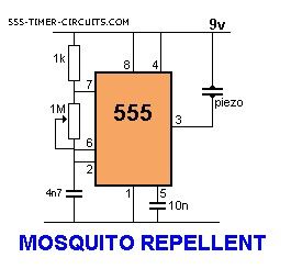
This circuit produces a tone above the human audible range and this is supposed to keep the mosquitoes away. You need a piezo diaphragm that will respond to 15kHz and these are very difficult to find.
(View)
View full Circuit Diagram | Comments | Reading(3105)
MODEL RAILWAY TIME Circuit
Published:2013/3/5 0:30:00 Author:Ecco | Keyword: MODEL RAILWAY, TIME Circuit
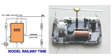
Here is a circuit that will convert any clock mechanism into Model Railway Time. For those who enjoy model railways, the ultimate is to have a fast clock to match the scale of the layout. This circuit will appear to make time fly by turning the seconds hand once every 6 seconds. The timing can be adjusted by changing the 47k. The electronics in the clock is disconnected from the coil and the circuit drives the coil directly. The circuit takes a lot more current than the original clock (1,000 times more) but this is one way to do the job without a sophisticated chip.
(View)
View full Circuit Diagram | Comments | Reading(1114)
LATCH Circuit
Published:2013/3/5 0:23:00 Author:Ecco | Keyword: LATCH
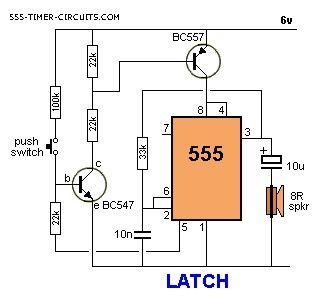
This circuit is a LATCH and remains ACTIVE when the push-button has been pressed for an INSTANT and released.
(View)
View full Circuit Diagram | Comments | Reading(2027)
LASER RAY Circuit
Published:2013/3/5 0:22:00 Author:Ecco | Keyword: LASER RAY
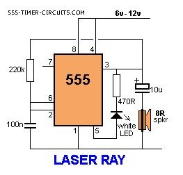
This circuit produces a weird Laser Ray sound and flashes a white LED at approx 5Hz:
(View)
View full Circuit Diagram | Comments | Reading(1221)
KNIGHT RIDER Circuit
Published:2013/3/5 0:21:00 Author:Ecco | Keyword: KNIGHT RIDER
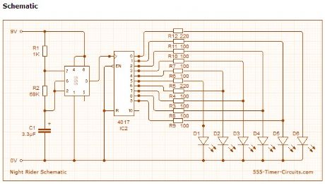
This circuit mimics the lights in knight rider's car. They flash one at a time chasing each other. Overview In the Knight Rider circuit, the 555 is wired as an oscillator (Astable mode). The output of the 555 is directly connected to the input of a 4017 decade counter. The input of the 4017 counter is called the CLOCK line. The 10 outputs Q0 to Q9 become active, one at a time, on the rising edge of the waveform from the 555. Each output can deliver about 20mA but a LED should not be connected to the output without a current-limiting resistor (100R or 220R). Using six 3mm LEDs, the display can be placed in the front of a model car to give a very realistic effect. The same outputs can be taken to driver transistors to produce a larger version of the display.
(View)
View full Circuit Diagram | Comments | Reading(2698)
HEE HAW SIREN Circuit
Published:2013/3/5 0:20:00 Author:Ecco | Keyword: HEE HAW SIREN
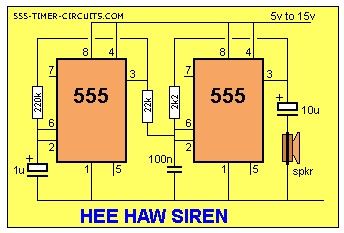
Build the circuit and listen. Change the resistors and capacitors to get all sorts of different results.
(View)
View full Circuit Diagram | Comments | Reading(1040)
DRIVING A RELAY Circuit
Published:2013/3/4 21:44:00 Author:Ecco | Keyword: DRIVING A RELAY
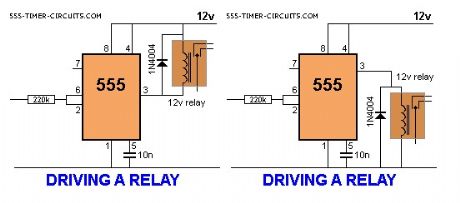
The 555 will activate a relay. When pins 2 and 6 are connected as an input, the chip requires only about 1uA to activate the output. This is equivalent to a gain of about 200,000,000 (200 million) and represents about 4 stages of amplification via transistors.In the first circuit,the output will be opposite to the input. The relay can be connected high or low as show in the second diagram. One point to note: The input must be higher than 2/3V for the output to be low and below 1/3V for the output to be high. This is called HYSTERESIS and prevents any noise on the input creating relay chatter.
(View)
View full Circuit Diagram | Comments | Reading(1240)
Hulda Clark's Zapper Circuit
Published:2013/3/4 21:34:00 Author:Ecco | Keyword: Hulda Clark's Zapper
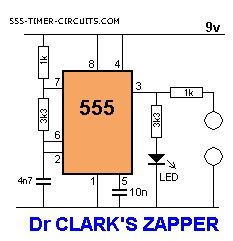

This is the circuit for Dr. Hulda Clark's Zapper, designed in 2003. The frequency is approximately 30kHz positive offset square wave. It has a red LED light that lights up when the unit is on. Perfect for regular zapping, extended zapping and other Hulda Clark related experiments. This device is used tocure, treat and prevent any disease. It will cure anything. Simply hold the two probes (one in each hand) for 5-10 minutes then rest for 20 minutes, then repeat two more times. Do this each day and you will be cured.
On the other side of the coin is the claim that Dr Hulda Clark is a complete quack. Here is a website called: Quackwatch. The second diagram shows the two copper tubes and the circuit in a plastic box. I am still at a loss to see how any energy can transfer from this quack machine, through the skin (50k skin resistance and 9v supply) and zap a bug in your intestine. It's a bit like saying I will kill all the mice in a haystack by stabbing the stack with a needle.
(View)
View full Circuit Diagram | Comments | Reading(0)
2nd Order Opamp Filters
Published:2013/3/4 20:59:00 Author:Ecco | Keyword: 2nd Order , Opamp , Filters
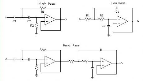
The figures below illustrate using opamps as active 2nd order filters. Three 2nd order filters are shown, low pass, high pass, and bandpass. Each of these filters will attenuate frequencies outside their passband at a rate of 12dB per octave or 1/4 the voltage amplitude for each octave of frequency increase or decrease outside the passband.
First order low or high pass cutoff frequency (-3dB point) = 1/(2pi*R*C) 2nd order low or high pass cutoff frequency (-3dB point) = 1/2pi(R1*R2*C1*C2)^.5 Example for 200 Hz cutoff frequency - R1=R2=7.95K, C1=C2=0.1uF
(View)
View full Circuit Diagram | Comments | Reading(1374)
Basic optocoupler circuit
Published:2013/3/1 2:39:00 Author:Ecco | Keyword: optocoupler
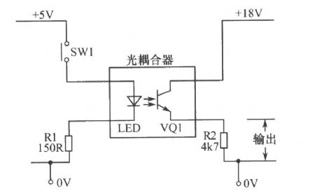
Basic optocoupler circuit is shown as figure.
(View)
View full Circuit Diagram | Comments | Reading(2168)
Leakage indicator circuit
Published:2013/2/28 1:20:00 Author:Ecco | Keyword: Leakage indicator
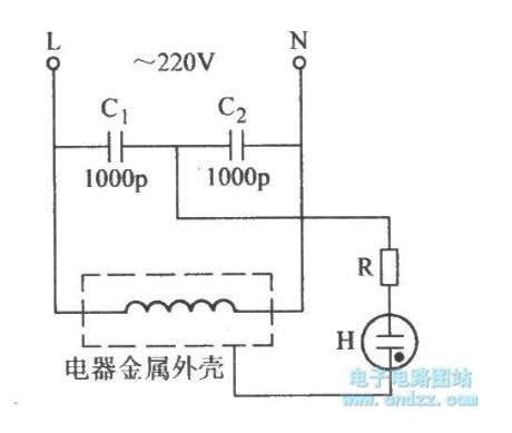
Leakage indicator circuit is shown as figure.
(View)
View full Circuit Diagram | Comments | Reading(961)
Glowplug Panel (b)
Published:2013/2/27 20:58:00 Author:muriel | Keyword: Glowplug Panel (b)

View full Circuit Diagram | Comments | Reading(692)
Electronic Canary (Doorbell)
Published:2013/2/27 20:54:00 Author:muriel | Keyword: Electronic Canary (Doorbell)
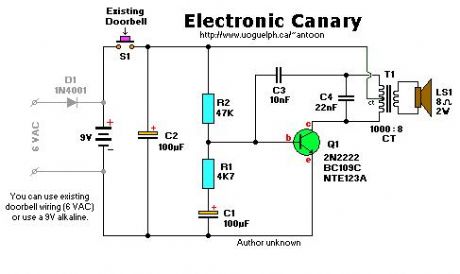
View full Circuit Diagram | Comments | Reading(1588)
| Pages:49/471 At 204142434445464748495051525354555657585960Under 20 |
Circuit Categories
power supply circuit
Amplifier Circuit
Basic Circuit
LED and Light Circuit
Sensor Circuit
Signal Processing
Electrical Equipment Circuit
Control Circuit
Remote Control Circuit
A/D-D/A Converter Circuit
Audio Circuit
Measuring and Test Circuit
Communication Circuit
Computer-Related Circuit
555 Circuit
Automotive Circuit
Repairing Circuit