
Wireless Receiver
Index
BMW fault code circuit diagram
Published:2014/3/5 20:22:00 Author: | Keyword: BMW fault code circuit diagram,
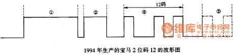
In 1994 BMW 3, 5, 7 series engine fault codes for two or three yards, as shown in figure:
(View)
View full Circuit Diagram | Comments | Reading(2213)
Santana 2000 car engine room on the left side of the wiring harness layout diagram
Published:2014/2/19 21:13:00 Author: | Keyword: Santana 2000 car engine room on the left side of the wiring harness layout diagram,
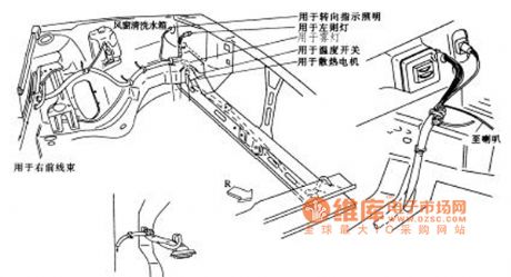
Santana 2000 car engine room as shown on the left side of the wiring harness layout diagram (View)
View full Circuit Diagram | Comments | Reading(1862)
桑塔纳2000轿车的发动机室照明线束布置电路图
Published:2014/2/19 21:04:00 Author: | Keyword: 桑塔纳2000轿车的发动机室照明线束布置电路图,
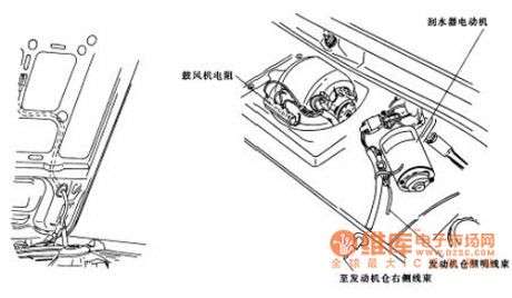
Santana 2000 car engine room as shown lighting wiring harness layout diagram (View)
View full Circuit Diagram | Comments | Reading(1944)
Santana 2000 car speed odometer sensor layout diagram
Published:2014/2/18 21:50:00 Author: | Keyword: Santana 2000 car speed odometer sensor layout diagram,

As shown santana 2000 car speed odometer sensor layout diagram (View)
View full Circuit Diagram | Comments | Reading(1867)
Santana 2000 car dashboard harness layout diagram
Published:2014/2/18 21:45:00 Author: | Keyword: Santana 2000 car dashboard harness layout diagram,
As shown santana 2000 car dashboard harness layout diagram (View)
View full Circuit Diagram | Comments | Reading(2087)
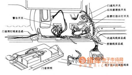
Santana 2000 car door harness layout diagram
Published:2014/2/18 21:40:00 Author: | Keyword: Santana 2000 car door harness layout diagram,
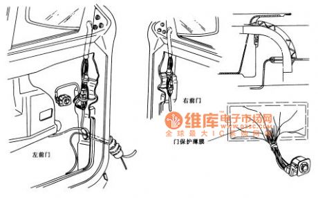
As is shown in santana 2000 car door harness layout diagram (View)
View full Circuit Diagram | Comments | Reading(1811)
Santana 2000 gsi - AT the dome light, visor light circuit diagram
Published:2014/2/9 20:59:00 Author: | Keyword: Santana 2000 gsi - AT the dome light, visor light circuit diagram,
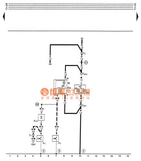
Figure santana 2000 gsi - AT the dome light, visor light circuit diagram
E3 - E56 alarm lamp switch inside the dome light lighting switch E57 - visor light switch F2 - in the left front door dome light contact switch F3 - right inside the front door, dome light contact switch K122 - inside the dome light protection diode T1i - inside the dome light harness connector, wiring harness and tail 1 needle, behind the central electric T1l - inside the dome light wiring harness and dashboard wiring harness connector, 1 needle, behind the central electric T2p - inside the dome light wiring harness plug connection with visor lamp, 2 needle, before the lights on the right side T26 - plug connection wiring harness and combination instrument board, 26, needle on combination instrument with delay function W - inside the dome light W3 - trunk floodlight W4 - visor lights (5) - ground, in the central electric star grounding claw pet-name ruby - on their own on the left of the anode ground wire,, dome light - cable harness, dome light, wiring harness (View)
View full Circuit Diagram | Comments | Reading(1759)
Santana 2000 gsi - AT the side lights, high brake lights, circuit diagram
Published:2014/2/9 20:57:00 Author: | Keyword: Santana 2000 gsi - AT the side lights, high brake lights, circuit diagram,
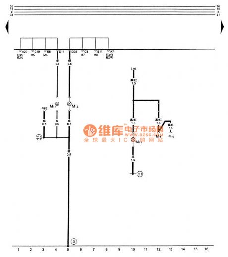


Figure santana 2000 gsi - AT the side lights, high brake lights, circuit diagram
E2 - turn signal switch E3 - alarm lamp switch F8 - force in low switch after the M5 - left turn signal before the M6 - left turn signal M7 - the right front turn signal M8 - right rear lights M9 left brake lamp M10 - right brake lamp M11 - the left turn signal M12 - the right turn signal M13 - high brake lights (5) - ground, in the central appliances on the left side of the star, grounding claw on - line - grounding cables inside the engine wiring harness right, within the tail wire harness (View)
View full Circuit Diagram | Comments | Reading(1685)
Santana 2000 gsi - an electric shake window machine, control set, the lock/wave window machine controller circuit diagram
Published:2014/2/7 19:56:00 Author: | Keyword: Santana 2000 gsi - an electric shake window machine, control set, the lock/wave window machine controller circuit diagram,
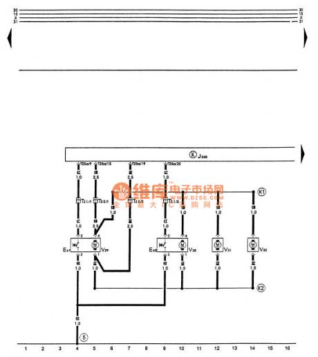


Figure santana 2000 gsi - AT electric shake window machine, control set, the lock/wave window machine controller circuit diagram
E61 - left front set control lock switch E62 - right front set control lock switch J330 - with lock/window machine controller, T2 Ⅰ above the glove box - remote/control wiring harnesses and wiring harness plug connection with door lock, lock 2 needle, T2 Ⅱ behind central electric remote control/control wiring harnesses and wiring harness plug connection with door lock, lock 2 needle, behind the central electric T25a - remote control/set control lock wire harness and set control lock/window machine controller plug connection, 25 needles, on with the lock/wave window machine controller V29 - V30 - right front left anterior with lock motor with motor after V31 - left with lock lock V32 - right rear with lock motor (5) - ground, in the central electrical grounding claws on - line on the left side of the star within the set control door lock wire - cable, within the set control door lock wire harness (View)
View full Circuit Diagram | Comments | Reading(1912)
Santana 2000 gsi - gate AT starting motor and reversing light relay circuit diagram
Published:2014/1/24 21:47:00 Author: | Keyword: Santana 2000 gsi - gate AT starting motor and reversing light relay circuit diagram,
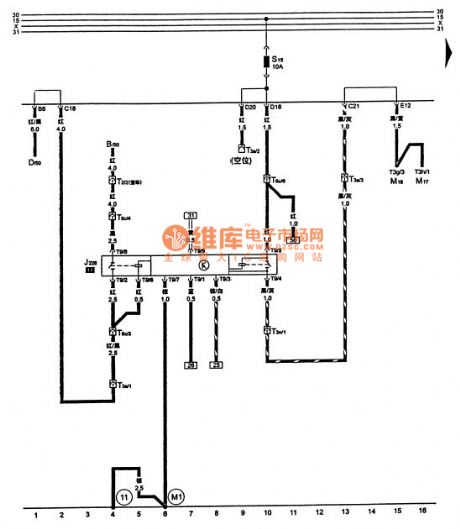

Tusangtana 2000GSi-AT starter motor lockout and reversing light relay circuit B-D-ignition starter switch J226-starter motor lockout and reversing light relay M16-M17-right-left reversing lights reversing lights S15-down lights, gear indicator shift lever lock solenoid fuse , 10A T2-engine wiring harness is connected to the generator harness connector, 2-pin, T3a-engine wiring harness and headlight harness plug is connected to the engine compartment in the middle frame, white, 3-pin, in the central electrical harness behind T3n-automatic transmission and the engine Right harness plug connection, white, 3-pin, in the central electrical harness behind T6c-automatic transmission and the engine wiring harness connector to connect the right, blue, 6-pin, behind the central electrical T9-automatic transmission harness and starter motor lockout and reversing light relay plug connector, 9-pin, in the central electrical - take place, in the right front seat underneath the car body - grounding cable in the automatic transmission wiring harness (View)
View full Circuit Diagram | Comments | Reading(1995)
Santana 2000 gsi - AT the control unit of automatic transmission, multi-function switch circuit diagram
Published:2014/1/24 20:21:00 Author: | Keyword: Santana 2000 gsi - AT the control unit of automatic transmission, multi-function switch circuit diagram,
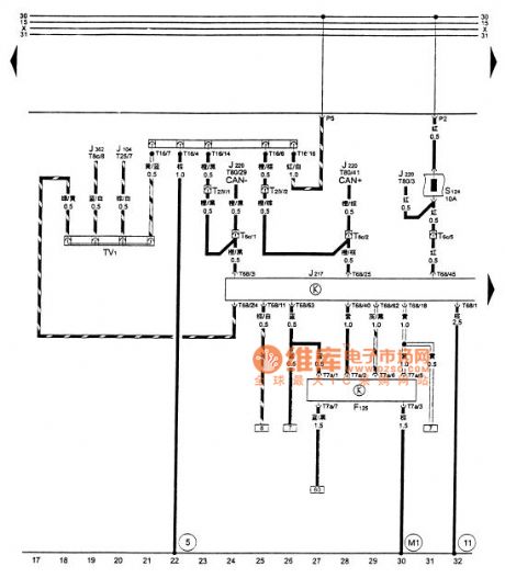
Tusangtana 2000GSi-AT automatic transmission control unit , multi-function switch circuit diagram
F125- multifunction switch in the rear of the transmission controller J217- J104-ABS automatic transmission control unit , in the right seat carpet J220-Motronic engine control unit , the air conditioner into the hood on the right side J362- alarm control unit , in the above S124- central electrical control unit of the engine , the automatic transmission control unit fuse , 10A T2 Ⅳ - automatic transmission harness is connected to the diagnostic connector harness , black, 2-pin , in the central rear T6c- automatic transmission of electrical harness and the right engine wiring harness, blue, 6-pin , T7a- automatic transmission wiring harness connector at the back of the center and the multi-function switch electrical plugs, black , 7-pin in the central electrical harness behind the dashboard T8c- alarm control unit with plug connection , black, 8-pin , the immobilizer control unit T16- fault diagnostic socket , black, 16-pin , in combination below T25-ABS and ABS controller harness connector plug meter , 25-pin , the ABS controller T68- automatic transmission and the transmission control unit harness connector , 68 pin on the transmission control unit T80- engine wiring harness , engine harness and engine control unit the right plug connector , 80-pin , the engine control unit TV1- line diagnostic socket attached to the 13th position on the central electrical ⑤ - take place in on the left side of the central star grounding prong electrical - ground cable harness in the automatic transmission - take place in the right front seat underneath the car body (View)
View full Circuit Diagram | Comments | Reading(2117)
Santana 2000 gsi - an automatic transmission control unit, solenoid valve, the transmission speed sensor, speed sensor circuit diagram
Published:2014/1/24 20:19:00 Author: | Keyword: Santana 2000 gsi - an automatic transmission control unit, solenoid valve, the transmission speed sensor, speed sensor circuit diagram,
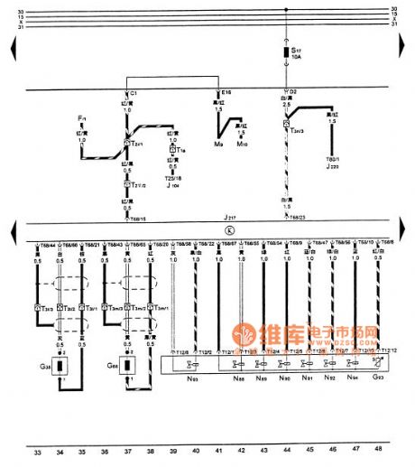
Tusangtana 2000GSi-AT automatic transmission control unit , solenoid valves, the transmission speed sensor, a vehicle speed sensor CircuitF- Brake Light Switch G38- transmission vehicle speed sensor , the transmission speed sensor on the left top of the G68- 1 , at the top right of the G93- transmission gearbox oil temperature sensor in the transmission of the flat -shaped wire controller J217- J104-ABS automatic transmission control unit , in the right seat carpet J220-Motronic engine control unit , the air conditioner into the hood to the right M9- M10- right- left brake light brake light N88- 1 N89- solenoid Valve solenoid Valve 2 N90- 3 N91- solenoid valve 4 N92- 5 N93- valve solenoid valve 6 N94- 7 S17- transmission control unit , engine control unit fuse , 10A T1a- headlights ABS harness connector and the harness connected to a pin, T2i- headlight harness and instrument panel harness electrical plug connector in the center back, white , 2-pin , in the central electrical behind T2 Ⅴ - automatic transmission harness and instrument panel harness plug connector , black, 2-pin , behind the central electrical T3l- automatic transmission and the transmission speed sensor wiring harness plug connectors attached harness , black, 3-pin , T3m- automatic transmission speed sensor harness and attach a harness plug connector at the rear of the automatic transmission , brown, 3-pin , automatic transmission rear T3n- automatic transmission harness Right connected to the engine wiring harness connector , white , 3-pin , in the central electrical harness behind T25-ABS and ABS controller plug connector , 25-pin , the ABS controller T68- automatic transmission and the transmission control unit harness plug connector , 68-pin , on the transmission control unit T80- engine wiring harness , engine harness and engine control unit the right plug connector , 80-pin , the engine control unit (View)
View full Circuit Diagram | Comments | Reading(2242)
Santana 2000 gsi - AT the control unit of automatic transmission, forced in low switch, shift lock check electromagnetic valve, gear lights circuit diagram
Published:2014/1/24 20:13:00 Author: | Keyword: Santana 2000 gsi - AT the control unit of automatic transmission, forced in low switch, shift lock check electromagnetic valve, gear lights circuit diagram,
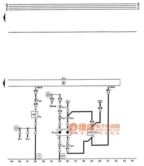


Figure santana 2000 gsi - AT the control unit of automatic transmission, forced in low switch, shift lock check electromagnetic valve, gear lights circuit diagram
E20 - the dashboard lighting regulator F8 - force in low switch, in the middle of the nacelle throttle zip L101 - shift lever on the lighting lamp and gear, the M11 in shift cover - the left turn signal M12 - the right turn signal J217 - automatic transmission control unit, in the right seat carpet K142 - shift lever below P/N warning lights, outpacing - shift in shift cover lock check electromagnetic valve, the shift lever on T2 Ⅴ - automatic transmission wire connected to the dashboard wiring harness plug, black, 2 needle, behind the central electric T3n - automatic transmission wire connected to the engine wiring harness plug right, white, 3 needles, behind the central electric T4g - automatic transmission wire connected to the gear indicator plug, 4 needle, below the shift lever T68 - automatic transmission wire connected to the transmission control unit plug, 68, on the transmission control unit (5) - ground, on the central electrical grounding on the left side of the star's paw - grounding cables, right at the engine wiring harness in D2 - cable (58) b - grounding cables within the dashboard harness, within the automatic transmission cable (View)
View full Circuit Diagram | Comments | Reading(1733)
Santana 2000 gsi - AT the ABS control unit, wheel speed sensor, electromagnetic valve circuit diagram
Published:2014/1/24 20:02:00 Author: | Keyword: Santana 2000 gsi - AT the ABS control unit, wheel speed sensor, electromagnetic valve circuit diagram,
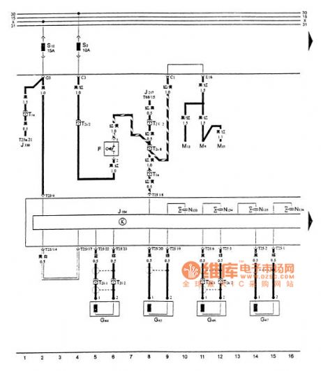
Tusangtana 2000GSi-AT ABS control unit , a wheel speed sensor, a circuit diagram of the solenoid valvesF- stop lamp switch after G44- G45- right wheel speed sensor front right , rear left wheel speed sensor G46- G47- left front wheel speed sensor wheel speed sensor controller J217- J104-ABS automatic transmission control unit , the carpet in the right seat Here J330- set locks shaking windows controller box at the top of the debris left brake lights M9- M10- M13- right brake lights brake lights N133-ABS Right backward oil solenoid valve N134-ABS Right out of the oil N135-ABS solenoid valve left backward N136-ABS oil out of the oil left rear brake light valve S2- fuse , 10A S12-ABS control , the automatic transmission control unit fuse , 15A T1a- headlights ABS harness connector and harness connection , a needle , in the central electrical harness behind T1e-ABS and electric window harness plug connector , a pin , T2i- headlight wiring harness connector at the back of the central instrument panel harness electrical connector , 2-pin , behind the central electrical T2l -ABS wiring harness connector and the right rear speed sensor connector , 2-pin , in the right rear seat following T2k-ABS harness and left rear speed sensor plug connection , two needles in the left rear seat below T2 Ⅴ - automatic transmission harness and instrument panel harness plug connector , black, 2-pin , in the central electrical harness behind T25-ABS and ABS controller plug connector , 25-pin , on the ABS controller T25a- remote / centralized control and centralized control harness connector lock lock / power window controller plugs, 25-pin , T68- automatic transmission and the transmission control unit harness connector is connected to the central control lock / power window controller , 68-pin , the transmission control unit (View)
View full Circuit Diagram | Comments | Reading(2357)
Santana 2000 gsi - AT the ABS control unit, ABS hydraulic pump and electromagnetic valve circuit diagram
Published:2014/1/23 23:22:00 Author: | Keyword: Santana 2000 gsi - AT the ABS control unit, ABS hydraulic pump and electromagnetic valve circuit diagram,
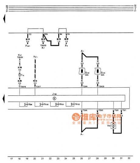
Figure santana 2000 gsi - AT the ABS control unit, ABS hydraulic pump and electromagnetic valve circuit diagram
A - battery F9 - hand brake lamp switch F34 - brake liquid level alarm switch J104 - ABS controller K7 instructions - hand brake and brake level warning light K47 - ABS warning light N99 - ABS right front feed N100 - ABS solenoid right front left anterior feed oil solenoid valve N101 - ABS solenoid valve N102 - ABS left before the oil T1k - dashboard harness with ABS solenoid wiring harness connector, 1 needle, behind the central electric T2j - ABS hydraulic pump and the control unit plug connection, 2 needle, T25 - ABS wiring harness on the ABS control unit and ABS controller plug connection, 25 needles, TV1 - diagnosis line socket on ABS controller, additional in central electric throne V64 13 - ABS hydraulic pump (View)
View full Circuit Diagram | Comments | Reading(1852)
Santana 2000 gsi saloon car air conditioning relay, air conditioning, A/C switch, speed switch, blower motor, cooling fans, room temperature switch, JinFengMen electromagnetic valve circuit diagram
Published:2014/1/23 21:59:00 Author: | Keyword: Santana 2000 gsi saloon car air conditioning relay, air conditioning, A/C switch, speed switch, blower motor, cooling fans, room temperature switch, JinFengMen electromagnetic valve circuit diagram,
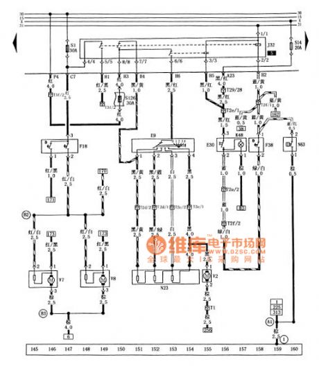


Tusangtana 2000GSi car air conditioning relay , air conditioning, A / C switch , speed switch , blower motor , cooling fan, temperature switches, circuit diagrams intake throttle valve
E9- speed switch E30- conditioned A / C switch F18- F38- fan thermal switch room air conditioner relay switch J32- K48- conditioned A / C switch indicator N23- N63- blower motor resistor into the throttle deceleration solenoid valve S1- cooling fan fuse ( without air conditioning when ) (30A) S14- relay fuse (20A) S126- air conditioning blower motor fuse (30A) T1- air conditioning blower motor harness and instrument panel harness plug connector ( 1 pin , back in the center of the circuit board ) T2c- conditioned steering and air conditioning blower motor harness wiring harness plug connector ( 2-pin , at the top of the acceleration pedal ) T2d- conditioned steering and air conditioning blower motor harness wiring harness plug connector ( 2-pin , at the top of the acceleration pedal ) T2e- dashboard switch harness and Air Conditioning manipulation harness plug connector ( 2-pin , behind the air conditioning control panel ) T2f- engine wiring harness and air conditioning manipulation harness plug connector ( 2-pin behind the central circuit board ) T3f- conditioned manipulate harness with the engine wiring harness plug connector ( 3-pin behind the central circuit board ) T29- dashboard instrument panel harness and switch harness plug connector ( 29 -pin , at the bottom of the instrument cluster ) V2- blower motor V7- V8- right- left cooling fan cooling fan - grounding cable ( in the engine wiring harness ) ① - ground cable ( engine control unit next to the car body ) - cable inside ( front headlight harness ) - ground cable ( inside front headlight harness ) (View)
View full Circuit Diagram | Comments | Reading(2395)
Santana 2000 gsi saloon car radiator fan controller, compressor trip relay, switch, combination switch, air conditioning cooling capacity water temperature control switch circuit diagram
Published:2014/1/22 20:25:00 Author: | Keyword: Santana 2000 gsi saloon car radiator fan controller, compressor trip relay, switch, combination switch, air conditioning cooling capacity water temperature control switch circuit diagram,
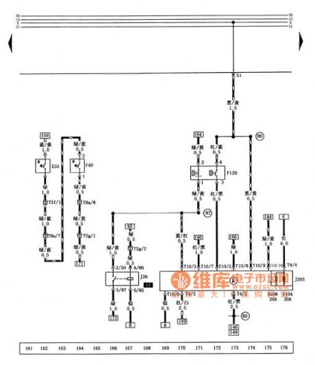


Figure santana 2000 gsi saloon car radiator fan controller, compressor trip relay, switch, combination switch, air conditioning cooling capacity water temperature control switch circuit diagram
E33 - F40 - air conditioning temperature control switch of cold energy F129 - J26 - compressor combination switch to cut off the relay J293 radiator fan controller S104 - radiator fan fuse when using air conditioning (top) (a) 30 S108 - radiator fan fuse (low gears when using air conditioning) T2g (20 a) - the engine wiring harness and headlamps wiring harness connector (2 needle, behind the central circuit board) T3f - air conditioning control wiring harness and the engine wiring harness connector (3 needles, behind the central circuit board) T4 - headlamps wiring harness plug connection with a radiator fan controller (4 pins on the radiator fan controller) T8a - engine wiring harness and the engine wiring harness plug connection right (8 needles, in the middle of the nacelle) on a support T10 - headlamps wiring harness plug connection with a radiator fan controller (10, on the radiator fan controller) - cable (within the headlamps harness) - (within the headlamps harness) - connecting the anode line (within the headlamps harness) (View)
View full Circuit Diagram | Comments | Reading(2093)
Santana 2000 gsi type car combination instrument circuit diagram
Published:2014/1/22 20:09:00 Author: | Keyword: Santana 2000 gsi type car combination instrument circuit diagram,
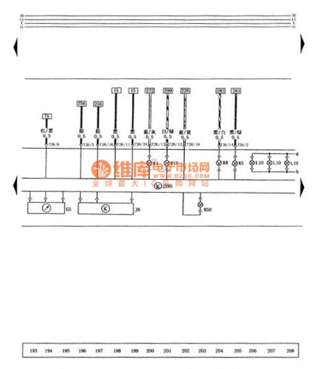
The figure of santana 2000 gsi saloon car combination instrument circuit diagram
The G5 - tachometer J6 - stabilizer J285 - combination instrument controller K1 - in light of K5 - right turn signals K8 - turn left to the lights k10/19 dated - after the wind window defrosting lamp K50 - lack of coolant warning lights L10 instrument lights T26 - plug connection wiring harness and combination instrument board (26 needles, on combination instrument) (View)
View full Circuit Diagram | Comments | Reading(1941)
Santana 2000 gsi type car combination instrument, radio, automatic antenna circuit diagram
Published:2014/1/22 3:43:00 Author: | Keyword: Santana 2000 gsi type car combination instrument, radio, automatic antenna circuit diagram,
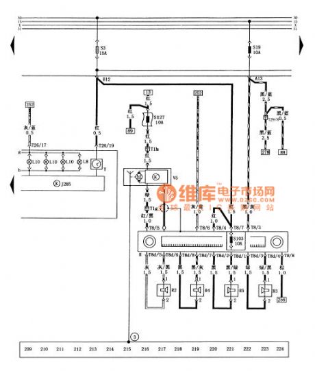
Figure combination instrument, santana 2000 gsi saloon car radios, automatic antenna circuit diagram
J285 combination instrument controller L8 - digital clock floodlight L10 - instrument lights R - cassette player R2 - left front speakers R3 - right front speakers R4 - left speaker after R5 - right rear speakers S3 - cigarette lighter, set control door locks, digital clock, after the dome light, reading lamp, suitcase light, visor light the fuse S19 (a) - a cassette player, lights, alarm control unit, the fuse (10 a) S103 - cassette player fuse (stop) (10 a) S127 - automatic antenna fuse (10 a) T1g - dashboard wiring harness and automatic antenna plug connection (1 needle, behind a cassette player) T1h - dashboard wiring harness and automatic antenna plug connection (1 needle, behind a cassette player) T8 - dashboard wire connected to the cassette player plug (8 needles, in the back of my cassette player) T8d - speaker wire connected to the cassette player plug (8 needles, in the back of my cassette player) T26 - plug connection wiring harness and combination instrument board (26 needles, on combination instrument) T29 - dashboard harness and dashboard switch harness connector (29 needle, below the combination instrument) V5 - automatic antenna Y - digital clock (3) - pick up location (near the antenna automatic car) (View)
View full Circuit Diagram | Comments | Reading(1141)
Santana 2000 gsi after car dome light, reading lamp, trunk lamp, visor light circuit diagram
Published:2014/1/22 3:38:00 Author: | Keyword: Santana 2000 gsi after car dome light, reading lamp, trunk lamp, visor light circuit diagram,
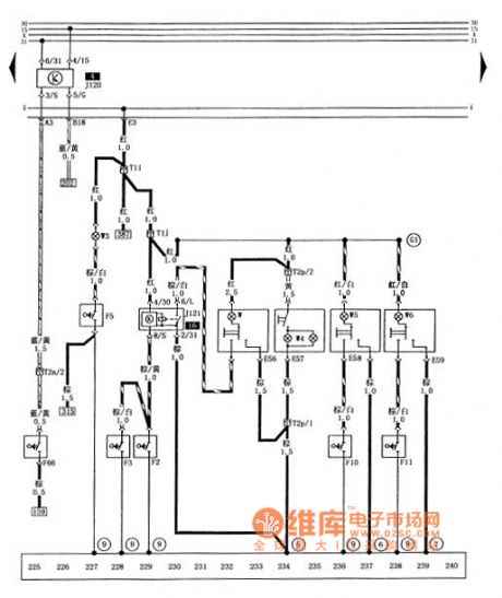

Figure santana 2000 gsi after car dome light, reading lamp, trunk lamp, visor light circuit diagram
E56 - inside the dome light lighting switch E57 - visor light switch E58 - left after reading lamp lighting switch E59 - right rear reading lamp lighting switch F2 - in the left front door dome light contact switch F3 - right inside the front door, dome light contact switch F5 - suitcase light contact switch F10 - left after reading light contact switch F11 - right rear reading light contact switch F66 - lack of coolant warning light switch J120 - cooling liquid level controller J121 - inside the dome light delay relay T1i - with door lock wire harness and tail plug connection (1 needle, behind the central circuit board) T1j - with door lock wire harness and dome light wiring harness connector (1 needle, behind the central circuit board) T2n - the engine wiring harness and dashboard wiring harness connector (2 needle, behind the central circuit board) T2p - inside the dome light wiring harness plug connection with visor lamp (2 needle, right in front of the roof) W - inside the dome light W3 - trunk floodlight W4 - visor light W5 - left after reading lamp W6 - right rear reading lamp (5) - pick up location (in the circuit board on the right side of the star grounding claw) 6 - pick up location (in the front left after a reading lamp on the roof) 7 - ground () on the posterior reading light in front of the roof pet-name ruby - its grounding - the positive cable (including dome light in the beam) (View)
View full Circuit Diagram | Comments | Reading(967)
| Pages:1/2 12 |
Circuit Categories
power supply circuit
Amplifier Circuit
Basic Circuit
LED and Light Circuit
Sensor Circuit
Signal Processing
Electrical Equipment Circuit
Control Circuit
Remote Control Circuit
A/D-D/A Converter Circuit
Audio Circuit
Measuring and Test Circuit
Communication Circuit
Computer-Related Circuit
555 Circuit
Automotive Circuit
Repairing Circuit