
Wireless Receiver
Index 2
Santana 2000 gsi type car headlights, parking lights, lights, tail lights, brake lights, nacelle, after lighting circuit diagram
Published:2014/1/21 20:07:00 Author: | Keyword: Santana 2000 gsi type car headlights, parking lights, lights, tail lights, brake lights, nacelle, after lighting circuit diagram,
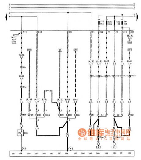
Figure of santana 2000 gsi saloon car headlights, parking lights, lights, tail lights, brake lights, nacelle, after lighting circuit diagram
F69 - nacelle light contact switch L1 - left headlamps L2 - right front headlight M1 - parking lights M3 left parking lights M2 - right - left tail lights M4 - right rear lights M6 - after the left turn signal M8 - right rear lights M9 left brake lamp M10 - right brake lamp M18 - nacelle lights integrated - right front headlight (in) the fuse (10 a) S10 - left headlamps (in) the fuse S21 (10 a) - (low), right front headlight fuse (10 a) S22 - left headlamps (low) fuse (10 a) T1c - headlamps wire connected to the engine wiring harness plug (1 needle, behind the central circuit board) T1d - the engine wiring harness and the engine compartment lighting wire connector (1 needle, in front of the wiper motor) T4d - headlamps wire connected to the right front headlight plug (4 needle, on the right front headlight) T4e - headlamps harness and left headlamps plug connection (4 needle, on the left headlights) today - ground combination (in the left rear light) on the left side of the car body earthing pet-name ruby - itself (View)
View full Circuit Diagram | Comments | Reading(991)
Santana 2000 gsi cars before the dimmer switch, alarm lamp switch, turn signal circuit diagram
Published:2014/1/21 19:57:00 Author: | Keyword: Santana 2000 gsi cars before the dimmer switch, alarm lamp switch, turn signal circuit diagram,
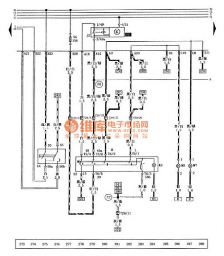


Figure santana 2000 gsi cars before the dimmer switch, alarm lamp switch, turn signal circuit diagram
E3 - alarm lamp switch E4 - dimmer switch J2 - turn signal relay K6 - alarm flash light is M5 - left front turn signal M7 - the right front turn signal S4 - alarm lights fuse T6 (15 a) - dashboard switch harness and alarming lamp switch plug connection (6 needle, on the lamp switch) T29 - dashboard harness and dashboard switch wiring harness connector (29 needle, below the combination instrument) - the positive connections (within the dashboard harness) - cable (within the dashboard switch wire) (View)
View full Circuit Diagram | Comments | Reading(774)
Turn signal switch, santana 2000 gsi saloon car parking lamp switch circuit diagram, fog light switch, dual tone horn
Published:2014/1/21 19:54:00 Author: | Keyword: Turn signal switch, santana 2000 gsi saloon car parking lamp switch circuit diagram, fog light switch, dual tone horn,
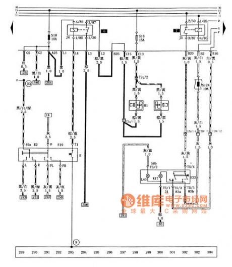

Figure of turn signal switch, santana 2000 gsi saloon car parking lamp switch circuit diagram, fog light switch, dual tone horn
E2 - turn signal switch E19 - stop lamp switch electronics - fog lamp switch H - dual tone horn switch H1 - dual tone horn J4 - horn relay J5 - fog lamps relay K17 - fog lamps light L40 - fog lamp switch lights S16 - horn fuse (15 a) S18 - the horn relay, light switch, ABS warning fuse S124 (10 a) - after the fog lights fuse (10 a) T2q - headlamps wire connected to the loudspeaker wiring harness plug (2 needle, over the loudspeaker) T5 - dashboard switch wiring harness and fog lamp switch plug connection (5 needles, in the fog lamp switch) T29 - dashboard harness and dashboard switch wiring harness connector (29 needle, below the combination instrument) pet-name ruby - its grounding - the positive connections (within the dashboard harness) (View)
View full Circuit Diagram | Comments | Reading(1194)
Santana 2000 gsi type car fog lamps, reversing lamp, license plate lamp, glove box lights, the speed sensor circuit diagram
Published:2014/1/16 22:34:00 Author: | Keyword: Santana 2000 gsi type car fog lamps, reversing lamp, license plate lamp, glove box lights, the speed sensor circuit diagram,
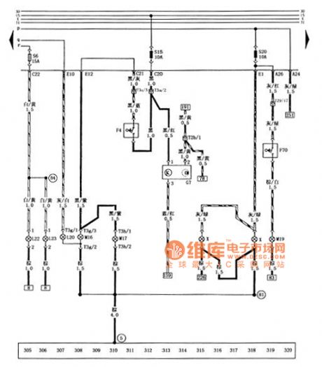
Figure of santana 2000 gsi saloon car fog lamps, reversing lamp, license plate lamp, glove box lights, the speed sensor circuit diagram
F4 - reversing lamp switch F70 - glove box light contact switch after the G7 - speed sensor L20 - fog lamps L22 - left front fog lamps L23 - right front fog lamps M16 - left back light M17 - right back light M19 - glove box lights S6 - front fog lamps fuse (15 a) S15 - reversing light fuse (10 a), speed sensor s20-40 lamp and glove box lighting the fuse (10 a) T2b - engine wiring harness and dashboard wiring harness connector (2 needle, on the left back light) T3a - the engine wiring harness and headlamps wiring harness connector (3 needles, behind the central circuit board) T3g - tail wire connected to the left back light plug (3 needles, on the left back light) T3h - tail wire connected to the right back light plug (3 needles, on the right back light) T29 - dashboard harness and dashboard switch wiring harness connector (29 needle, below the combination instrument) X - license plate lamp (5) - ground () on the circuit board on the right side of star grounding claw - the positive connections (within the headlamps harness) - grounding cables (within the tail wire) (View)
View full Circuit Diagram | Comments | Reading(1111)
Santana 2000 gsi cars before the wind window wiper, before the wind window cleaners circuit diagram
Published:2014/1/16 18:36:00 Author: | Keyword: Santana 2000 gsi cars before the wind window wiper, before the wind window cleaners circuit diagram,
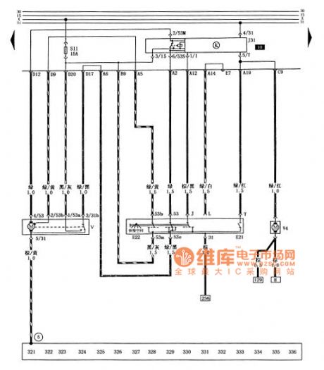
Figure santana 2000 gsi cars before the wind window wiper, before the wind window cleaners circuit diagram
E21 - the wind window cleaning pump switch E22 - before the wind window wiper switch J31 - wiper relay S11 - before the wind window wiper, cleaner fuse (15 a) V - the wind window wiper motor V4 - before the wind window cleaning pump (5) - pick up location (in the circuit board on the right side of the star grounding claw) (View)
View full Circuit Diagram | Comments | Reading(817)
Santana 2000 gsi type car electric circuit diagram window machine 1
Published:2014/1/15 18:33:00 Author: | Keyword: Santana 2000 gsi type car electric circuit diagram window machine 1,
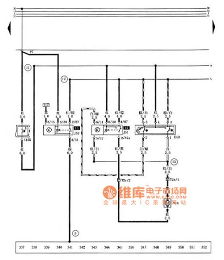
Tusangtana 2000GSi car electric window circuit diagram
E40-shaking windows switch J51-shaking windows down automatically relay J52-shaking windows delay relay S125-electric window executive protection T2r-electric window and electric window harness plug connector (2-pin, in Left front door) V14-left front window regulator motor ⑤ - ground (on the right side of the central star circuit board ground claw) - positive cable (in the electric window harness) - connection cable (in power shake harness the windows machine) - cable (in the electric window harness) (View)
View full Circuit Diagram | Comments | Reading(959)
Santana 2000 gsi type car electric circuit diagram window machine 2
Published:2014/1/15 18:32:00 Author: | Keyword: Santana 2000 gsi type car electric circuit diagram window machine 2,
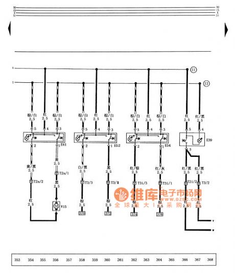
Tusangtana 2000GSi car electric window circuit diagram
E39-shaking windows safety switch (back door) E41-shaking windows switch (front left) E52-shaking windows switch (left rear) E54-shaking windows switch (right rear) T2s-electric window harness and electric window machine plug connector (2-pin, in the right front door) T3-electric window with the left rear window regulator harness plug connector (3-pin in the left rear door) T3i-electric window harness with the right rear window regulator plug connection (3-pin, in the right rear door) V15-right front window regulator motor - positive cable (in the electric window harness) - connection cable (in the electric window harness) (View)
View full Circuit Diagram | Comments | Reading(1183)
Santana 2000 gsi type car electric shake window machine, electric rearview mirror circuit diagram
Published:2014/1/15 18:30:00 Author: | Keyword: Santana 2000 gsi type car electric shake window machine, electric rearview mirror circuit diagram,
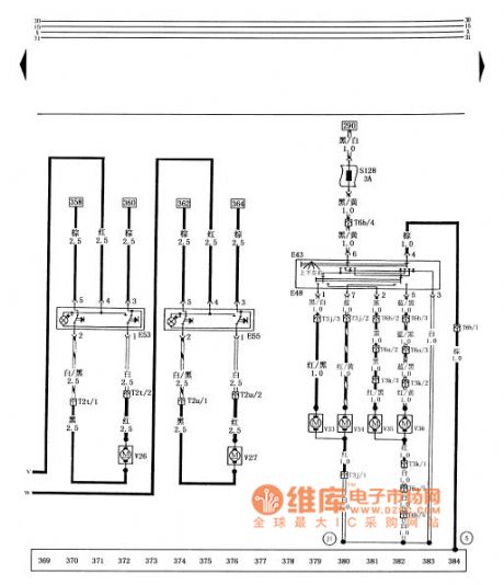
Tusangtana 2000GSi car electric window , electric mirrors schematics
E43- E48- electric mirror adjustment switch on switch electric mirrors converter E53- shaking on the left rear door window machine switch E55- right rear door window regulator switch S128- electric mirrors Fuse (3A) T2t- left rear windows shake switches and shaking windows machine motor plug connector ( 2-pin in the left rear door ) T2u- right rear power window switch and shaking windows machine motor plug connector ( 2-pin , in the right rear door ) T3j- left and left- front harness electric Mirrors plug connector ( 3-pin in the front left door ) T3k- right front door and right electric mirrors harness plug connector ( 3-pin , in the right front door ) T6a- electric mirrors harness and right front door harness plug connection ( 6-pin on the right side glove box ) T6b- electric mirrors harness and right front door harness plug connector ( 6 pin in the left center of the circuit board ) after the left rear window regulator V26- V27- motor motor Right shaking windows V33- left and down to adjust electric mirrors electric mirrors left motor V34- V35- right- left-right adjustment of the motor up and down to adjust electric mirrors electric motor V36- right- left mirror adjustment motor ⑤ - ground ( Right in the center of the circuit board side star ground claw ) ( 13 ) - cable ( in the left front door wiring harness ) (View)
View full Circuit Diagram | Comments | Reading(1004)
Santana 2000GSi car central control door locks, rear window defroster circuit diagram
Published:2014/1/13 18:36:00 Author: | Keyword: Santana 2000GSi car central control door locks, rear window defroster circuit diagram,
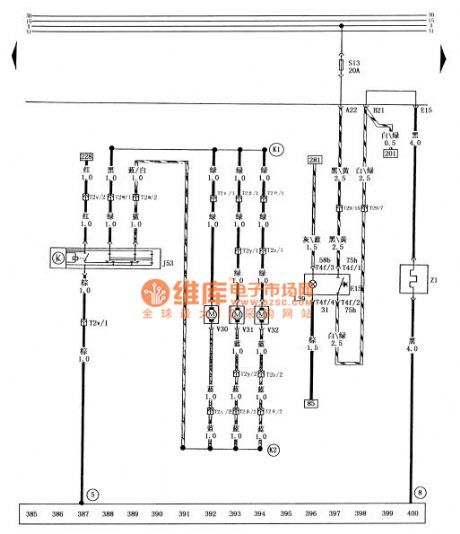
Tusangtana 2000GSi sedan centralized control door locks, rear window defroster circuit diagram
E15- rear window defroster switch J53- controlled lock controller L39- set rear window defroster switch lights rear window defroster S13- fuse (20A) T2v- left front door lock set additional control wiring harness and set central locking harness plug connector ( 2-pin in the front left door ) T2w- left front door lock set additional controls and centralized control door lock harness harness plug connector ( 2-pin in the front left door ) T2x- right front door lock set additional control wiring harness connection ( 2-pin , in the right front door ) and centralized control door lock harness plugs T2y- left rear door locks additional set of harness and left rear door attached harness plug connector ( 2-pin in the left rear door ) T2z- right rear door locks additional set Additional wiring harness and right rear door harness plug connector ( 2-pin , in the right rear door ) T2β- attach the harness and set the left rear door locks harness plug connector ( 2-pin , on the outside of the driver's seat under the carpet ) T2θ- attach the harness and set the right rear door lock harness plug connector ( 2-pin , in the passenger seat carpet outside ) T4f- dashboard switch harness with rear window defroster switch plug connector ( 4-pin on the rear window defroster switch ) T29- dashboard harness and instrument panel switch harness plug connector ( 29 -pin , at the bottom of the instrument cluster ) V30- set locks the front right , rear left set the motor V31- V32- controlled lock the right set of motor control motor Z1- lock rear window defroster ⑤ - ground ( on the right paw central star ground on the circuit board ) ⑧ - ground ( in the left rear combination lamps left the car body ) K1- cable ( in the central control door lock harness ) K2- cable ( the set Central locking wiring harness ) (View)
View full Circuit Diagram | Comments | Reading(1154)
The House Finch Direct Conversion Tube Receiver
Published:2013/3/7 3:14:00 Author:Ecco | Keyword: House Finch, Direct Conversion Tube , Receiver

After building the Little Chickadee 6U8A vacuum tube 80 meter CW transmitter project, your author decided that it would be a good idea to build a companion 80 meter tube CW receiver. A direct-conversion design seemed like a good approach since it is fairly simple and is effective for receiving morse code. Not wanting to reinvent the wheel, the Internet was searched for vacuum tube direct conversion designs. Surprisingly, no other projects were found. The online projects that were found were either solid state designs or regenerative tube circuits.
Nature abhors a vacuum, but not necessarily a vacuum tube so this project was born. Of course, designing something new with vacuum tubes is not an entirely rational pursuit. Rationalizations aside, tube projects are fun, nostalgic and they glow in the dark. This project was a lot more difficult to complete than originally anticipated, but solving the many problems was certainly educational. Those who copy this design should have a much easier time getting the circuit running. It should be farily straightforward to adapt this design to other HF ham bands by changing the resonant sections in the front end filter and oscillator.
The 6U8A audio amp project was already functioning nicely and was perfect for the audio amplifier stage in a communications receiver. The 6U8A seemed like a good choice for the mixer and oscillator circuits. In fact, that's how the 6U8A is usually used. One can think of the 6U8A as a vacuum tube equivalent (sort of) of the popular NE602 IC. The first version of this receiver used just two 6U8A tubes, it worked (barely), but there was a need for additional audio gain and isolation between the antenna and the mixer. The 6C4 preamp tube and the 6BA6 RF amplifier tubes were added to solve these problems.
The receiver is divided into three physical sections, 1: the RF filter and amplifier, 2: the mixer, oscillator and audio filters and 3: the audio amplifier. A few extra grid bias resistors and filament hum cancelation resistors were added so that the individual sections can be disconnected and operated in a stand-alone mode. This also allows the sections to be used as stand-alone modules for other projects. An external power supply provides 6.3VAC for the filaments and 250VDC for the B+ supply, the supply can be shared between this receiver and the companion Little Chickadee transmitter.
(View)
View full Circuit Diagram | Comments | Reading(3406)
Radio control car receiver principle circuit diagram
Published:2011/5/11 1:52:00 Author:Rebekka | Keyword: Radio control car receiver
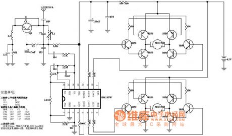
Here is the diagram of radio controlcarreceiverprinciple circuit.
Notes:The choice of transistor Q1 and the bias resistorQ1 1815 9018R1 240K 100K
The choice of the high-frequency parameters partFrequency C1 C2 L227M 35P 30P 10uH35M 30P 30P 8.2uH40M 30P 20P 5.1uH49M 20P 15P 3.3uH
The production method of L1In the diameter of 5mm, use Enameled wire diameter of 0.5 to intensively wound the skeleton with a core. Make appropriate changes according to the frequency.
(View)
View full Circuit Diagram | Comments | Reading(5913)
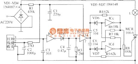
Appliances infrared remote control receiver circuit diagram
Published:2011/4/20 22:31:00 Author:Rebekka | Keyword: Appliances , infrared remote control, receiver
View full Circuit Diagram | Comments | Reading(1291)
Composed of MC3372 and MC341196D 45MHz band radio receiver circuit diagram
Published:2011/4/21 4:20:00 Author:Rebekka | Keyword: band radio receiver

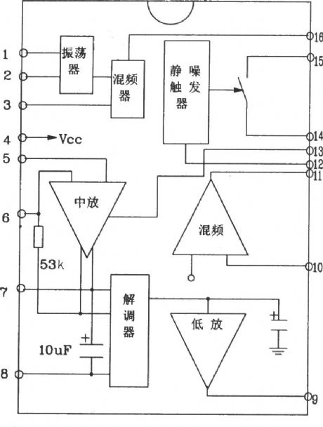
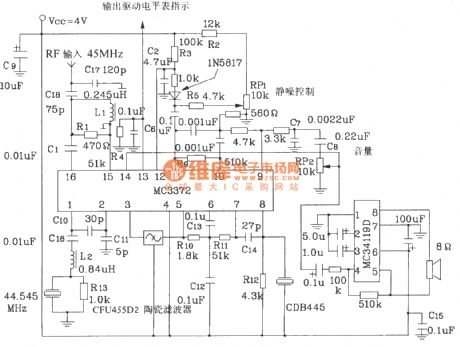
MC3373-specific integrated circuit radio receiver is low-power narrowband FM receiving device of Motorola. It operates up to 100MHz.
MC3372 pin function diagram form.
MC3372 internal block diagram.
45MHz band radio receiver circuit composed of MC3372 and MC341196D.
(View)
View full Circuit Diagram | Comments | Reading(3042)
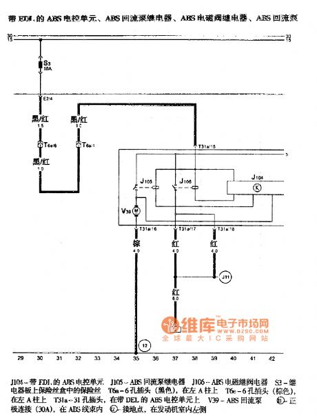
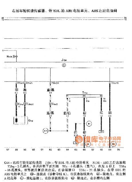
Gaoer ABS circuit
Published:2011/4/14 22:24:00 Author:Jessie | Keyword: ABS

View full Circuit Diagram | Comments | Reading(771)
| Pages:2/2 12 |
Circuit Categories
power supply circuit
Amplifier Circuit
Basic Circuit
LED and Light Circuit
Sensor Circuit
Signal Processing
Electrical Equipment Circuit
Control Circuit
Remote Control Circuit
A/D-D/A Converter Circuit
Audio Circuit
Measuring and Test Circuit
Communication Circuit
Computer-Related Circuit
555 Circuit
Automotive Circuit
Repairing Circuit