
Wireless Transmitter
Index
BMW 20 pin diagnosis in engine compartment on the left side of the circuit diagram
Published:2014/1/7 19:56:00 Author: | Keyword: BMW 20 pin diagnosis in engine compartment on the left side of the circuit diagram,

BMW 20 pin diagnosis in engine compartment on the left side of the circuit diagram
(View)
View full Circuit Diagram | Comments | Reading(838)
BMW series engine fault codes before 1988 Diagram
Published:2014/1/7 19:55:00 Author: | Keyword: BMW series engine fault codes before 1988 Diagram,
BMW series engine fault codes before 1988 Diagram (View)
View full Circuit Diagram | Comments | Reading(774)
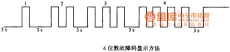
BMW 3,5,7 series engine fault codes for the two yards or three yards circuit diagram of a waveform
Published:2014/1/7 19:53:00 Author: | Keyword: BMW 3,5,7 series engine fault codes for the two yards or three yards circuit diagram of a waveform,
BMW 3,5,7 series engine fault codes for the two yards or three yards circuit diagram of a waveform
(View)
View full Circuit Diagram | Comments | Reading(830)
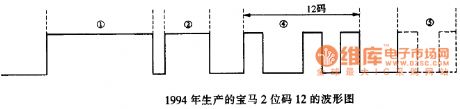
BMW 3, 5, 7 series engine fault codes for two or three yards waveform diagram 2
Published:2014/1/7 19:52:00 Author: | Keyword: BMW 3, 5, 7 series engine fault codes for two or three yards waveform diagram 2,

BMW 3, 5, 7 series engine fault codes for two or three yards waveform diagram 2
(View)
View full Circuit Diagram | Comments | Reading(796)
BMW solenoid valve solenoid valve position circuit diagram
Published:2014/1/6 19:50:00 Author: | Keyword: BMW solenoid valve solenoid valve position circuit diagram,
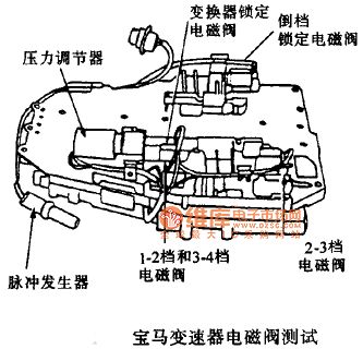
BMW solenoid valve solenoid valve position circuit diagram
(View)
View full Circuit Diagram | Comments | Reading(943)
BMW BMW3 series A4S 55-310 - r pin transmission circuit diagram
Published:2014/1/6 19:48:00 Author: | Keyword: BMW BMW3 series A4S 55-310 - r pin transmission circuit diagram,
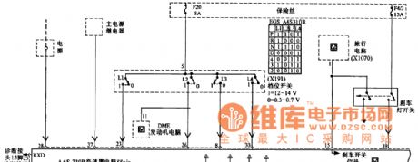
BMW BMW3 series A4S 55-310 - r pin transmission circuit diagram
(View)
View full Circuit Diagram | Comments | Reading(940)
BMW 97 328 I wiper washing circuit diagram (Canada)
Published:2013/12/17 1:59:00 Author: | Keyword: BMW 97 328 I wiper washing circuit diagram (Canada),
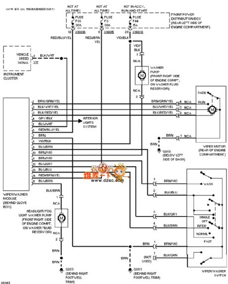
BMW 97 328 I wiper washing circuit diagram (Canada) as shown below:
(View)
View full Circuit Diagram | Comments | Reading(1023)
BMW 97 328 I transmission circuit diagram
Published:2013/12/17 1:46:00 Author: | Keyword: BMW 97 328 I transmission circuit diagram,
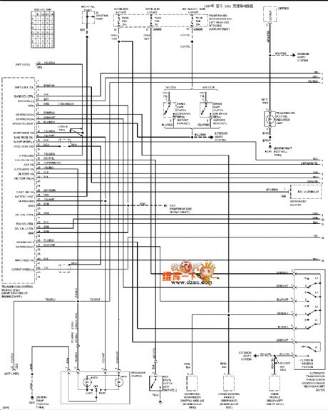
BMW 97 328 I transmission circuit diagram as shown below:
(View)
View full Circuit Diagram | Comments | Reading(938)
BMW 97 328 I visor circuit diagram
Published:2013/12/16 2:12:00 Author: | Keyword: BMW 97 328 I visor circuit diagram,
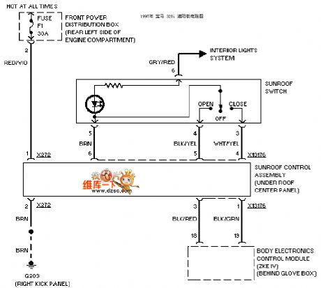
BMW 97 328 I visor circuit diagram as shown below:
(View)
View full Circuit Diagram | Comments | Reading(950)
BMW 97 328 I gear interlock circuit diagram
Published:2013/12/13 2:03:00 Author: | Keyword: BMW 97 328 I gear interlock circuit diagram ,
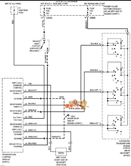
BMW 97 328 I gear interlock circuit diagram as shown below:
(View)
View full Circuit Diagram | Comments | Reading(1016)
BMW 97 328 I electric seat circuit diagram
Published:2013/12/13 1:58:00 Author: | Keyword: BMW 97 328 I electric seat circuit diagram,
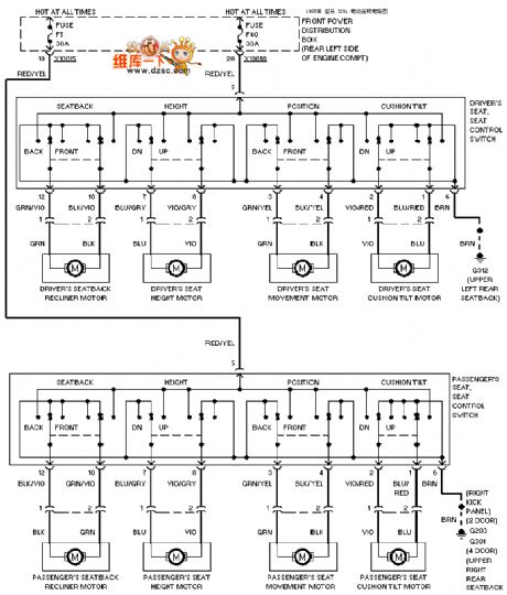
BMW 97 328 I electric seat circuit diagram as shown below:
(View)
View full Circuit Diagram | Comments | Reading(1200)
Basic radio transmission circuit with surface acoustic wave resonator SAW
Published:2012/11/15 21:03:00 Author:Ecco | Keyword: Basic radio transmission , surface acoustic wave, resonator , SAW
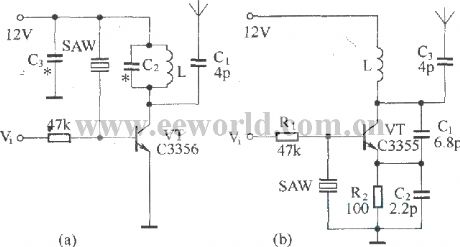
Figure (a) shows a basic circuit of the transistor UHF radio transmitter with surface acoustic wave resonator (SAW), and the SAW is used as a positive feedback element connected between the transistor VT base and LC network in parallel. Figure (b) shows another basic transistor UHF radio transmitter circuit with the surface acoustic wave resonator, in this circuit, SAW is connected between the transistor's base and emitter; the phase relationship between them is 180 degree.
(View)
View full Circuit Diagram | Comments | Reading(6205)
Basic low power AM transmitter
Published:2012/9/18 21:26:00 Author:Ecco | Keyword: Basic, low power , AM transmitter
This transmitter?is basic but allows transmission of audio to an AM radio. It consists of an RF?oscillator operating in the AM broadcast band, together with a modulator stage,?which mixes the incoming audio and the RF. A signal appears on the output, which?has an AM component that can be picked up on a nearby AM radio receiver.
The transmitter consists of?oscillator stage Q1 and modulator/buffer stage Q2. Q1 is biased via R1, R2, and R3.?L1, C3, and C4 form the tank circuit with feedback network C3-C4 providing feedback?to the emitter of Q1. RF voltage at the junction of C3 and L1 drives buffer/modulator stage Q2. Q2 is biased by base current produced by RF rectification in the?base emitter junction of Q2. C6 is an RF and AF bypass capacitor. C9, C10, and L2?form the tank circuit for the collector of Q2. RF is taken from the junction of C9 and?C10 and fed to a?short-wire?antenna. Audio is fed to modulator Q2 via C8 and isolation?resistor R5 and mixes with the RF signal in the collector circuit of Q2, producing?a signal that has sum and difference frequencies if the RF carrier and AF input ?along with the carrier signal.
An AM signal appears at?the collector of Q2. Audio with an RMS voltage equal to about 0.7 times the collector?voltage of Q2 is needed for full modulation of the output.?Because of the high level of audio needed, the modulation obtained from this circuit?is somewhat limited with conventional audio sources because several volts of?audio into a few hundred ohms is needed. The circuit demonstrates the principle of?an AM transmitter, however, and with a suitable audio drive level, produces a well modulated?AM signal.5 Responses to “Basic low power AM transmitter”
(View)
View full Circuit Diagram | Comments | Reading(1995)
2 Watts FM transmitter
Published:2012/9/13 20:52:00 Author:Ecco | Keyword: 2 Watts, FM transmitter
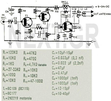
This is a nice 2 Watts FM transmitter. It has a Super-Sensitive pre-amplification with BC109 and BC177 with more than 100% signal modulation. The job finish the 2N2219 by Motorola. For the Coils you should use 1mm wire(enameled), L1= 3 turns - 10mm diameter, L2= 1 turn - 10mm diameter. R9 trimmer controls the modulation gain. The tunning is easy by controlling C9 trimmer (88-108 MHz). The RFC J should be the VK220J with ferrite (VK200 is not suitable).
Source: NEXT.GR (View)
View full Circuit Diagram | Comments | Reading(3121)
FM surveillance BuG Transmitter
Published:2012/9/13 20:50:00 Author:Ecco | Keyword: FM surveillance BuG , Transmitter
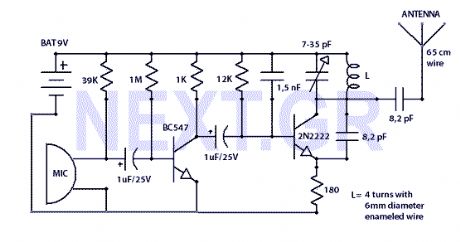
The Circuit shown can transmit voice to exceptionally good range. Tune trimmer to hear the signal to your near radio. Frequency range is 88-108 MHz. Max current consumption is 30mA. You can power the bug with a 9Volt Battery, or you can plug a power supply to feed in 9-12 Volts.
Source: NEXT.GR (View)
View full Circuit Diagram | Comments | Reading(2830)
Simple Infra-Red Transmitter/reciever Shematics
Published:2012/9/13 3:53:00 Author:Ecco | Keyword: Simple , Infra-Red Transmitter, reciever

This 1 channel infrared transmitter/receiver remote control is the cheapest and simplest you can find. The transmitter transmits a sequence of pulses on 36 KHz frequency carrier. The diodes are Schottky type because of their low voltage drop (only 0.2V). The ripple counter 74HC4060 contains an oscillator which controls the frequency carrier to be 36KHz.
Source: NEXT.GR (View)
View full Circuit Diagram | Comments | Reading(2351)
Quality FM-TV micro transmitter 40-200 Mhz
Published:2012/9/12 20:52:00 Author:Ecco | Keyword: Quality, FM-TV, micro transmitter, 40-200 Mhz
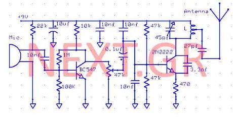
This Transmitter can be powered by a battery 9V (not more than 12V). You can connect your music source where the microphone is or use a simple condenser microphone. The range of signal can reach 400 meters in open air. The wide range of frequency is up to you. Tune it at FM band (88-108) or TV band 40-80Mhz. Play with the Coil and the variable capacitor to tune it to any frequency you want as long as you got the receiver. (View)
View full Circuit Diagram | Comments | Reading(2812)
DTMF wireless paging system circuit diagram
Published:2011/10/18 1:36:00 Author:Rebekka | Keyword: wireless paging system , DTMF
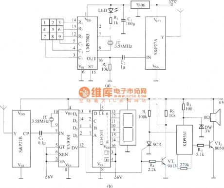
IT usesDTMF encoder output dual tone multi-frequency coded signal to modulate the transmitted carrier frequency. It can form a DTMF encoded radio paging system. The circuit uses DTMF encoding UM97085 and decoding circuit YN9101 circuit to form a small wireless paging system for small internal paging. It is convenient and economical. It is shown in the figure, in which (a) shows the radio transmitting DTMF encoding circuit. Figure (b) shows the radio receiver demodulation, DTMF decoding and reproducing sound signal circuits. (View)
View full Circuit Diagram | Comments | Reading(5295)
The basic radio SR circuit diagram composed of F36-F/J
Published:2011/10/18 1:31:00 Author:Rebekka | Keyword: basic radio SR
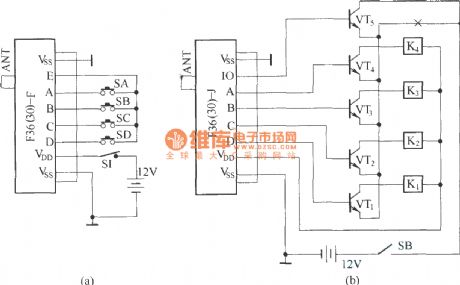
F36-F / J is a pair of digitally encoded radio frequency transceiver components, and the named carrier frequency is 36MHz. F36-F / J components are used in encoding / decoding circuit PT2262/PT2272.
F36-F / J constitutes the basic radio transceiver circuit, whichis shown as above. (View)
View full Circuit Diagram | Comments | Reading(3618)
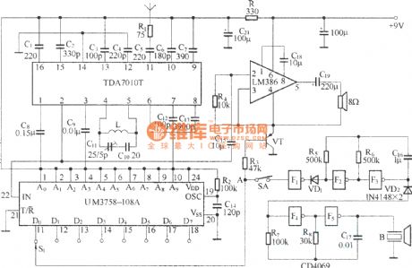
Small wireless call system circuit diagram (BA1401/TDA7010T)
Published:2011/10/18 2:07:00 Author:Rebekka | Keyword: Small wireless call system
View full Circuit Diagram | Comments | Reading(2964)
| Pages:1/2 12 |
Circuit Categories
power supply circuit
Amplifier Circuit
Basic Circuit
LED and Light Circuit
Sensor Circuit
Signal Processing
Electrical Equipment Circuit
Control Circuit
Remote Control Circuit
A/D-D/A Converter Circuit
Audio Circuit
Measuring and Test Circuit
Communication Circuit
Computer-Related Circuit
555 Circuit
Automotive Circuit
Repairing Circuit