
Index 11
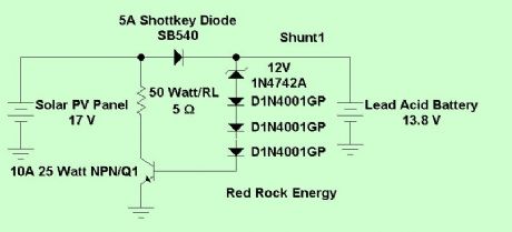
Simple Shunt Charge Controller
Published:2013/7/5 1:52:00 Author:muriel | Keyword: Simple Shunt , Charge, Controller
View full Circuit Diagram | Comments | Reading(1310)
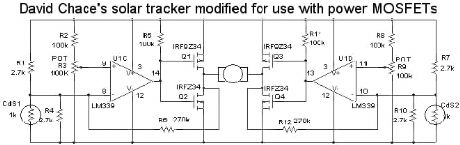
Analog Solar Tracker Schematic
Published:2013/7/5 1:52:00 Author:muriel | Keyword: Analog , Solar, Tracker Schematic
View full Circuit Diagram | Comments | Reading(5402)
LEDFAST Acting Analog Solar Tracker
Published:2013/7/5 1:48:00 Author:muriel | Keyword: LEDFAST , Acting Analog, Solar Tracker
View full Circuit Diagram | Comments | Reading(2143)
LEDCooker3
Published:2013/7/5 1:45:00 Author:muriel | Keyword: LEDCooker3
View full Circuit Diagram | Comments | Reading(1022)
Solar Cooker Solar Trackers 2
Published:2013/7/5 1:45:00 Author:muriel | Keyword: Solar Cooker , Solar Trackers

View full Circuit Diagram | Comments | Reading(1179)
Solar Cooker Solar Trackers
Published:2013/7/5 1:45:00 Author:muriel | Keyword: Solar , Cooker, Solar Trackers
View full Circuit Diagram | Comments | Reading(1362)
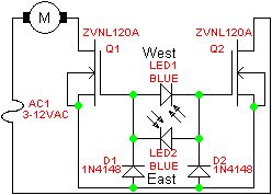
LEDAC a Very Simple Solar Tracker Powered by an AC Power Source
Published:2013/7/5 1:44:00 Author:muriel | Keyword: LEDAC, Very Simple, Solar, Tracker, Powered, AC Power Source
View full Circuit Diagram | Comments | Reading(2818)
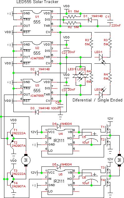
LED555 Timer Based Solar Tracker
Published:2013/7/5 1:41:00 Author:muriel | Keyword: LED555, Timer, Solar Tracker
View full Circuit Diagram | Comments | Reading(1755)
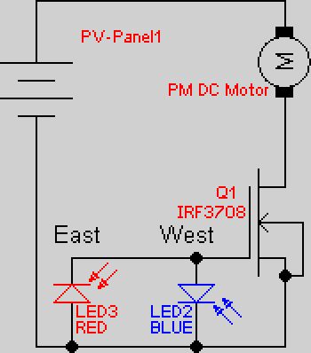
LED5S12V Simplified LED low power tracker
Published:2013/7/5 1:37:00 Author:muriel | Keyword: LED5S12V , Simplified , LED , low power , tracker
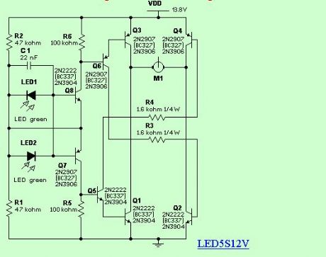
This circuit uses small switching transistors. The maximum motor drive current is limited to about 100mA maximum at 12V. (View)
View full Circuit Diagram | Comments | Reading(971)
LED5S5V Simplified LED low power tracker
Published:2013/7/5 1:36:00 Author:muriel | Keyword: LED5S5V, Simplified, LED , low power tracker

I was looking for a much lower cost tracker for low power applications. One of these applications is a small lighting heliostat. This circuit uses small switching transistors. The maximum motor drive current is limited to about 250mA maximum at 5V.
I've tested the circuit on voltages from 3V to 21V. With some component changes it should be useful to 63V in a 36V PV panel system although I haven't tried this yet. With higher voltage and the use of heat sinks on the bridge transistors much higher currents should be possible. (View)
View full Circuit Diagram | Comments | Reading(1347)
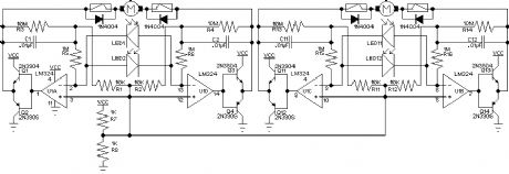
LED2 LED Sensor Relay Tracker Schematic
Published:2013/7/5 1:35:00 Author:muriel | Keyword: LED2 , LED, Sensor , Relay, Tracker Schematic

Circuit 1 tends to chatter the relays under certain lighting conditions as there is no built in hysteresis. This version uses a Schmitt trigger hex inverter circuit to eliminate the chatter. It works better but is more complex.
Note! R4 and R5 are used to force parking when it gets dark. If parking is not desired don't use R4 and R5. Parking may not be desired in low power consumption applications.Also, the parking resistors, R4 and R5, reduce sensitivity a bit. (View)
View full Circuit Diagram | Comments | Reading(1081)
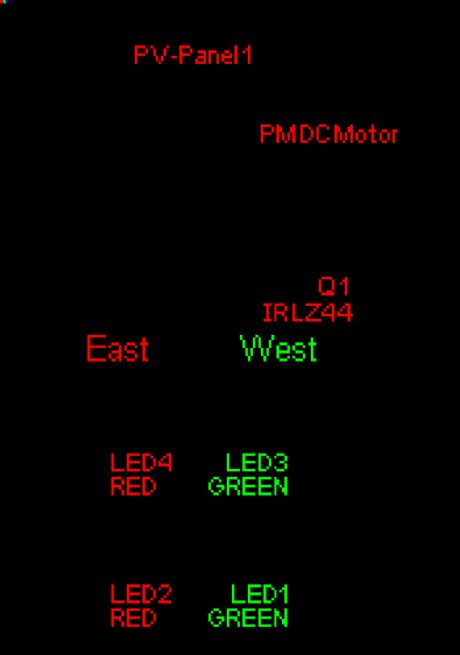
LED1 LED Sensor Relay Tracker Schematic
Published:2013/7/5 1:35:00 Author:muriel | Keyword: LED1 , LED , Sensor, Relay , Tracker Schematic
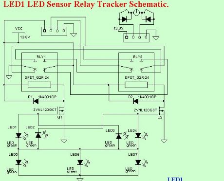
I have been looking for truly low cost and yet accurate conventional solar trackers. The CdS tracker is pretty good but lacks accuracy and sensitivity. I was thinking about using PV cells as the sensor. I was experimenting with LEDs and noticed they generate voltage in sunlight.
Bingo! This got me to thinking.
They generate quite a bit of voltage. The green ones generate about 1.65V, some as much a 1.74V. Not the piddley .55 volts of a silicon PV cell. How is this so? Well, it turns out green LEDs are made from Gallium Phosphide, a semiconductor with a much higher bandgap voltage.
I thought I had invented the use of LEDs as PV cells as I had never heard of this effect before. Well, after some investigating I found a number of references to this. The guys that had done the most work in this area were the people form the BEAM project. They make tiny solar powered robots and some used LED photo sensors.
I had been using a very low threshold MOSFET in a TO-92 package, BS107PT. The threshold is about 1.5V. If I put two LEDs back to back, one fighting the other, the one with more light intensity wins. I thought I could use this to switch the MOSFET. And it worked.
By using one LED as a sort of power supply and the back to back pair connected from it to the MOSFET gate the circuit is complete. (This I have not seen elsewhere.) My implementation uses three power supply LEDs, aimed East, Up, and West. The sensor LEDs are aimed about 90°s from each other and at about 45°s either side of up. Of course the easterly pair will be a little to the East and the westerly pair a little to the West. This makes the center have a dead zone where tracking stops.
The circuit is quite sensitive. It brings the panel back to the East just after sun rise. The accuracy is quite good. You can calibrate the sensor by bending or aiming the LEDs a bit.
While the proof of concept is good it will burn the relay contacts, similar to that on the Cadmium Sulfide tracker. This is caused by the relays being turned on or off slowly. It melted the plastic case on the relays. (View)
View full Circuit Diagram | Comments | Reading(1222)
How Limit Switches Operate
Published:2013/7/5 1:34:00 Author:muriel | Keyword: Limit Switches
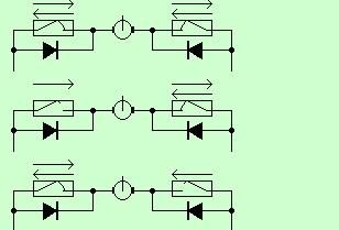
Limit switches are essential for servo motor operation with solar trackers. I made this diagram to help explain how they work.
Top. Normal operation between limit switches.Middle. The left limit switch has opened to stop movement to the left. To move to the right again the diode conducts current that allows movement to the right.Bottom. The right limit switch has opened to stop movement to the right. To move to the left again the diode conducts current that allows movement to the left.
Sellect a diode or rectifier rated at the maximum motor current plus some margine. Also the voltage should be at leat 100V and preferably 200V.
Needles to say, the limit switch must operate before the mechanical limits are reached. If the mechanical stop is reached before the switch the motor can draw quite high currents and can destroy the solar tracker. (View)
View full Circuit Diagram | Comments | Reading(1220)
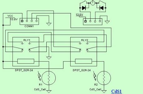
Cadmium Sulfide Relay Tracker Schematic
Published:2013/7/5 1:33:00 Author:muriel | Keyword: Cadmium Sulfide, Relay , Tracker Schematic
View full Circuit Diagram | Comments | Reading(914)
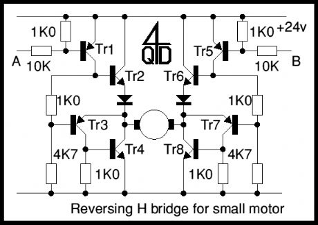
H bridge switch
Published:2013/7/3 3:03:00 Author:muriel | Keyword: H bridge switch
View full Circuit Diagram | Comments | Reading(1140)
H Bridge Motor control
Published:2013/7/3 3:01:00 Author:muriel | Keyword: H Bridge Motor control

View full Circuit Diagram | Comments | Reading(1090)
Transistor Control
Published:2013/7/3 2:54:00 Author:muriel | Keyword: Transistor Control
View full Circuit Diagram | Comments | Reading(940)
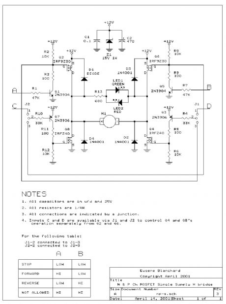
Alternating CW & CCW Motor Driver
Published:2013/7/3 2:53:00 Author:muriel | Keyword: Alternating, CW & CCW , Motor , Driver
View full Circuit Diagram | Comments | Reading(1473)
Power switching circuits
Published:2013/7/3 2:48:00 Author:muriel | Keyword: Power switching circuits
The Zero Volt Diode -- a synchronous rectifier circuit by Wilf Rigter:
The Zero Volt Diode (ZVD) is a circuit useful in a variety of applications including solar chargers of all types. It is a novel circuit in which a power MOSFET acts like a very low voltage drop diode that switches state at 0V and which is used to conduct negative current from drain to source.
In D1 type solar engines, a low loss diode can be used to charge a cap to the open circuit voltage of the solar cell and used in solar battery chargers, the battery is charged at the maximum rate when the source voltage is highest. The diode must be used in series with the solar panel or else the cap or battery would discharge through the solar panel when the panel voltage drops below the stored voltage. The diode or equivalent polarity sensitive switch is therefore essential to solar chargers.
Most diodes used in BEAM SEs and solar chargers are Silicon diodes like the 1N4001 which have a voltage drop of 0.6V to 1V at currents up to 1A. More efficient diodes for currents form >100mA to tens of amps applications are the Schottky type rectifiers with a voltage drop of from 200mV to 1000mV depending on the current level. For <100mA applications a Germanium diode can used with 200mV or less drop.
This voltage drop issue is important in competition solar engines since you would like to have the maximum voltage to charge the cap and supply the load (low diode drop) and keep the charge stored on the cap when the lightlevel drops (leakage current cut off) and the SE triggers. Moreover, since the energy in the cap is proportional to the square of the voltage even the small voltage drop of a diode reduces available energy. One obvious simple improvement over the original D1 design is to substitute a Ge 1N34A diode (Radio Shack) instead of the Si 1N4001 diode.
An ideal diode would have zero voltage drop. While a straight hookup of the solar cell has minimum voltage drop it leaks if the light drops and any real diode has a forward voltage drop. What to do?
The solution is to use a MOSFET as a rectifier just like the synchronous rectifier applications in voltage converters. The MOSFET should be switched ON when the solar voltage is larger than the capacitor or battery voltage and switch OFF when the solar voltage is lower than the stored voltage.
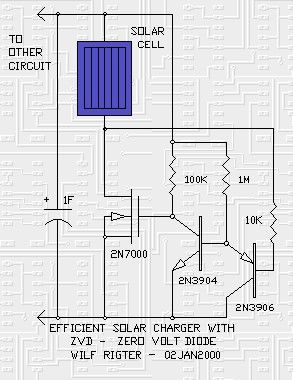
Here is a little design for charging capacitors from solar cells with zero voltage drop at the end of the charge cycle. It can be easily scaled to higher currents by changing the 2N7000 for a larger MOSFET. If a parallel load is present, the circuit also delivers maximum voltage with minimum insertion loss from the solar cell. The MOSFET turns on when the voltage difference is zero and turns off when the solar voltage drops less than 100mV below the cap or battery.
The NPN transistor is normally ON when the cap voltage is more than .6V and this clamps the gate of the 2N7000 which is turned OFF. The PNP transistor is connected to the negative terminal of the solar panel and when the voltage on that terminal drops below 0V the PNP turns ON. This in turn turns the NPN OFF and the 2N7000 turns ON. MOSFETs have an interesting characteristic in that they act like bi-directional switches, so the 2N7000 is perfectly happy to have it's drain conduct a negative current to the 0V line. When the voltage on the negative terminal of the solar panel is more positive than 0V the PNP turns OFF and the NPN ON and the 2N7000 turns off with the drain voltage positive with respect to the source voltage and 0V line. Since the 2N7000 does not turn on until the gate voltage is more than 2V (in practice: higher according to the data book) a logic FET with a lower gate turn on voltage would be preferred. In any case the MOSFET has a integral reverse diode from drain to source which will carry the current until the voltage on the cap reaches 2V at which point the MOSFET turns on and the forward voltage drops to a few 10s of mV. (View)
View full Circuit Diagram | Comments | Reading(1271)
simple single-motor driver
Published:2013/6/27 21:16:00 Author:muriel | Keyword: simple single-motor driver
View full Circuit Diagram | Comments | Reading(1021)
| Pages:11/312 1234567891011121314151617181920Under 20 |
Circuit Categories
power supply circuit
Amplifier Circuit
Basic Circuit
LED and Light Circuit
Sensor Circuit
Signal Processing
Electrical Equipment Circuit
Control Circuit
Remote Control Circuit
A/D-D/A Converter Circuit
Audio Circuit
Measuring and Test Circuit
Communication Circuit
Computer-Related Circuit
555 Circuit
Automotive Circuit
Repairing Circuit