
Index 309
Gas-sensitive controller circuit
Published:2011/3/29 22:26:00 Author:Jessie | Keyword: Gas-sensitive controller
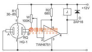
This paper uses gas sensitive components and TWH8751 to compose gas-sensitive controller, it can be widely used in coal mine, chemical industry, metallurgy and family, etc. When RQ touch combustible gas, theresistance drops, when the gas concentrations reach a certainlevel, 8751will connect andmake relay work, R1 is work current to limit RQ, which can lengthen the service life of RQ components. W is the sensitivity controllor, according to some gas concentrations, it adjusts to a certain value, make the decline of RQ, TWH8751 connected and work, achieve purpose of control.
(View)
View full Circuit Diagram | Comments | Reading(353)
Pyroelectric infrared switch circuit diagram
Published:2011/3/30 22:07:00 Author:Jessie | Keyword: Pyroelectric infrared switch
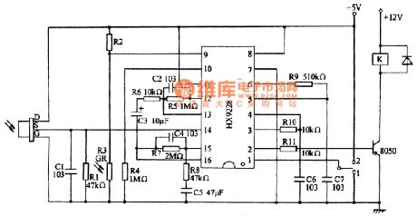
When infrared sensor processing special chip HX9228receives infrared sensor's output signal, after completing linear amplification, two-way amplitude discrimination, signal processing, delay timing, blockade timing, its pin 2 outputs high-level make triode 8050 conduction, drive relay K suck closes. Then the relay contacts control corresponding controlled object. In the diagram, R2 adjustes choiceaccording to environmental brightness, when thepin 9 is low potential, chip can't trigger.
(View)
View full Circuit Diagram | Comments | Reading(1245)
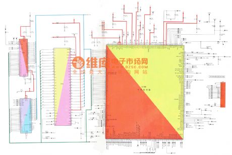
MOTOROLA V60 mobile phone circuit principle diagram
Published:2011/3/30 22:47:00 Author:Jessie | Keyword: mobile phone principle
View full Circuit Diagram | Comments | Reading(431)
Combustible gas leak alarm circuit diagram
Published:2011/3/29 21:31:00 Author:Jessie | Keyword: Combustible gas, leak alarm
View full Circuit Diagram | Comments | Reading(774)
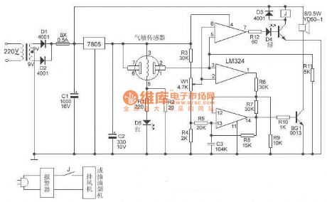
Gas sensor fire alarm circuit diagram
Published:2011/3/30 21:34:00 Author:Jessie | Keyword: Gas sensor, fire alarm
View full Circuit Diagram | Comments | Reading(1214)
Touch switch circuit diagram
Published:2011/3/30 20:40:00 Author:Jessie | Keyword: Touch switch
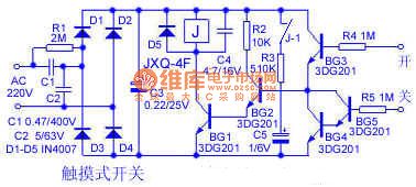
In beginning, J inthe state of losing electricity. When using, handle the open, the human body induction signal amplified by BG1 ~BG3, J sucks close, meanwhile J - 1 sucks and make J self-locked. When need to shut off, handle the close, the human body induction signal amplified by BG4 ~BG5, bypass BG2 base current, J release, circuit is back again. When making circuit BG1 ~ BG5's BVceo > 30V, BG1, BG3, BG4, BG5's β>50, BG2's β>80, the unit of capacitance is µF/V. After installeditcan work without debugging. When this switch device shuts off the power, power consumption is close to zero, turn-on'spower < 0.5 W, switch devices using voltage range> 130V ~ 250V.
(View)
View full Circuit Diagram | Comments | Reading(555)
Automatic hand washing device circuit with SM9576
Published:2011/3/29 20:34:00 Author:Jessie | Keyword: hand washing device
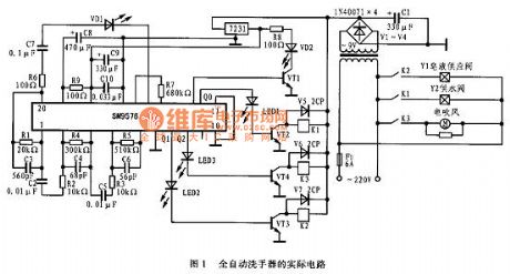
Automatic hand washing device circuit is shownin the figure 1. 220V AC power is step-down by transformer, V1 ~ V4 bridge rectifier, C1 is filteredto 9VDC power, this power supply to relay K1 ~ K3 as work power, then become 3V DC powersupplied toSM9576 as work power. The core device of automatic hand washing device circuit is SM9576, it contains infraredtransmit drive circuit and infrared receiving amplify circuit, its reception is decided by the size of the capacity of the sensitivity, when the C7 is in 0.01 ~ 0.1 u F, the receiving distance is changingbewteen 5 ~ 25cm.
(View)
View full Circuit Diagram | Comments | Reading(900)
Infrared micro-computer automatical pump fluid hardware design circuit
Published:2011/3/23 2:42:00 Author:Joan | Keyword: micro-computer , automatical pump fluid , Infrared pump fluid

The design uses a Microchip PIC16C54 microcontroller, selects GR40101 GD1611 infrared emitting diodes and silicon PIN photodiode as the infrared transmit and receive devices, chooses micro motors QDB-30-3.0 LCD driver as the pump. The system uses one-touch mode to complete suspension, setting the pump fluid volume and other functions.The circuit design uses power-saving mode with standby current less than 100μA, provides the necessary 500mA load current for micro-motor, and can monitor battery voltage, alarm when the battery is under voltage. System schematic is shown below.
In above figure, TX (infrared emission diode), R1, R5, Q4 constitute infrared emission circuit. Microcontroller port RA1 outputs certain frequency pulse to control transistor Q4 on or off, so as to control the transmit frequency of the infrared emission diode TX. MCU RA3 port provides power for the transmitter circuit for energy conservation. When RA1 port launchs pulse, RA3 port set high, firing circuit is power on. RX (infrared receiver), R2, R11, R12, R13, R16, Q6, C3 constitute infrared receiver circuit. RX receives infrared pulse, which is amplified by Q6 after being shaped.
Receiving circuit magnification must be strictly controlled to ensure the infrared reflection receive distance of about 10cm. Receiving circuit power is provided by the MCU port RB1. After the pulse launch, RB1 port sets high. R6, R7, R8, Q3 constitute battery voltage monitoring circuit. When the supply voltage drops to a certain value, Q3 cuts off, MCU port RB3 sets high, the circuit alarms for under-voltage. D2, D3, R9, R10, Q1, Q5 constitute the motor power supply circuit to provide the necessary 3V voltage and 500mA load current for the micro-motor. When needs to drive motor pump fluid, the microcontroller port RB2 output low voltage, Q emitter provides power supply for the motor. D1, C4, Q2, R3 constitute motor control circuit, it provides power supply for the motor first when pumps fluid, and then microcontroller port RA2 output high voltage to drive motor running. The LED is the work status indicator. The single function SW key, can set the pump fluid volume, pump fluid suspension, manual pump fluid and other functions. (View)
View full Circuit Diagram | Comments | Reading(989)
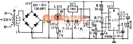
The exposure time control circuit diagram
Published:2011/3/30 21:49:00 Author:Ecco | Keyword: Time exposure
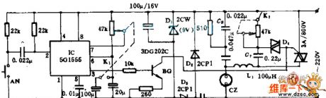
To assure the quality of the photogragh, this device can satisfy the shutterbug to control the time of exposure. It has the advantages of high accuracy in time controlling, having universal function such as time exposure, light-dimmer, pressure regulating and so on. Enlarging bulb or iron, electric blanket and lamp. The electric applianceses, such as electric fan and dynamo. etc. can be connected to the output socket CZ, and the output is controlled by the silicon capacity. For example, the pure resistive load can provide the power with 600 W; capacitive or inductive burden make the output be smaller than 300w.
(View)
View full Circuit Diagram | Comments | Reading(516)
Automatic instructions protection circuit diagram
Published:2011/3/29 20:05:00 Author:Ecco | Keyword: Automatic instructions protection
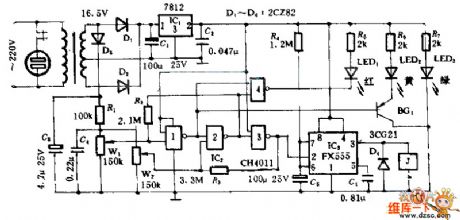
When the electric supply in the circuitry is higher than the limit set by W1, LED 2 will be lit, door 2 will be closed, output 1, J pulled in, closed contact is disconnected. That could realize the purpose of temporary protection to interruption. When the electric supply is lower than the limit, door 4 opened, LED 1 lit, the output of door 3 is 0 , J pulled in. That also could realize the purpose of temporary protection to interruption. (View)
View full Circuit Diagram | Comments | Reading(544)
Relay measurment circuit diagram
Published:2011/3/20 22:56:00 Author:Ecco | Keyword: Relay measurment
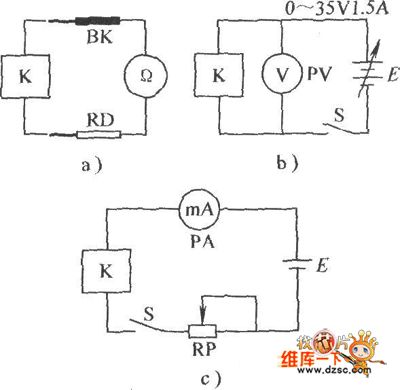
Relay measurment circuit diagram is as below:
(View)
View full Circuit Diagram | Comments | Reading(531)
Alarm control keyboard circuit diagram
Published:2011/3/20 22:54:00 Author:Ecco | Keyword: Alarm, control keyboard
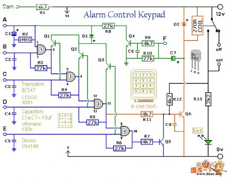
Alarm control keyboard circuit diagram is as below:
(View)
View full Circuit Diagram | Comments | Reading(420)
Optically controlled circuitry diagram
Published:2011/3/20 22:55:00 Author:Ecco | Keyword: Optically controlled circuitry
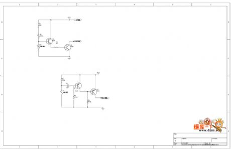
Optically controlled circuitry diagram is as below:
(View)
View full Circuit Diagram | Comments | Reading(487)
Control and display circuit diagram of Koltai T - 9328 amplifier
Published:2011/3/28 22:16:00 Author:Ecco | Keyword: Control circuit, display circuit , Koltai amplifier
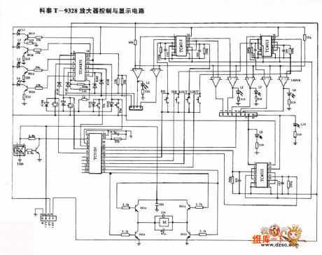
Control and display circuit diagram of Koltai T - 9328 amplifier is as below:
(View)
View full Circuit Diagram | Comments | Reading(338)
Series motor full-wave control circuit
Published:2011/3/21 1:38:00 Author:Allen | Keyword: Series motor, full-wave control


The circuit adopts transistor phase-shift trigger and one-way thyristor to control the full-wave voltage of series motor circuit, so it can control motor speed at a wide range. Resistor R5 in series on one-way thyristor main circuit constitutes negative feedback, which can stabilize the speed. The values of R5 is 0.1-1 Ω. Br diode rectifier bridge can convert AC to DC.
(View)
View full Circuit Diagram | Comments | Reading(890)
PWM speed control circuit of electric bicycles
Published:2011/3/21 1:37:00 Author:Allen | Keyword: PWM, electric bicycle

View full Circuit Diagram | Comments | Reading(3277)
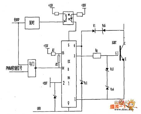
Switching tube drive circuit diagram composed of EXB 841
Published:2011/3/28 3:37:00 Author:Nicole | Keyword: switching tube drive
View full Circuit Diagram | Comments | Reading(374)
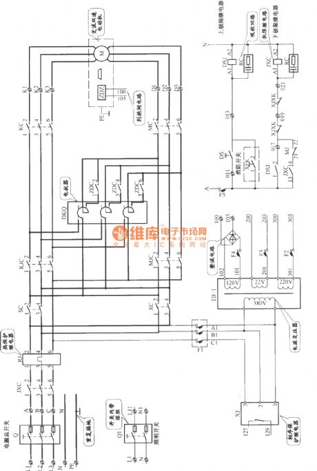
Shenyang sanyo AC double speed elevator main circuit
Published:2011/3/25 3:49:00 Author:Jessie | Keyword: AC, double speed elevator
View full Circuit Diagram | Comments | Reading(621)
Thyristor which isolated by integrated triggers and transformers circuit
Published:2011/3/24 20:49:00 Author:Jessie | Keyword: Thyristor, integrated triggers, transformers
In this circuit, the control section and grid are segregated. The output pulse after amplified by trigger amplifier adds to pulse transformer primary winding. Secondary windings can supply wide 550μs triggering pulse, trigger current is 1A, trigger voltage is 2V. (View)
View full Circuit Diagram | Comments | Reading(664)
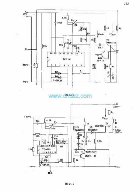
Product closed tube control circuit with integrated flip-flop TcA780
Published:2011/3/24 21:08:00 Author:Jessie | Keyword: Product closed tube, control, integrated flip-flop

This circuit's control range is 0~180°, output power is 0~400W. Integrated trigger power supplied byresistance R1, diode D1, capacitance C1 and regulator tube. Adjusting potentiometer Rp1 can control voltage changs from 0 to 8V, and the control angle adjusts from 0°to 180°.
(View)
View full Circuit Diagram | Comments | Reading(1005)
| Pages:309/312 At 20301302303304305306307308309310311312 |
Circuit Categories
power supply circuit
Amplifier Circuit
Basic Circuit
LED and Light Circuit
Sensor Circuit
Signal Processing
Electrical Equipment Circuit
Control Circuit
Remote Control Circuit
A/D-D/A Converter Circuit
Audio Circuit
Measuring and Test Circuit
Communication Circuit
Computer-Related Circuit
555 Circuit
Automotive Circuit
Repairing Circuit