
Control Circuit
Index 237
Agricultural irrigation line burglar alarm circuit diagram 2
Published:2011/6/16 3:47:00 Author:Lucas | Keyword: Agricultural, irrigation line , burglar alarm
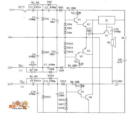
The agricultural irrigation line burglar alarm circuit is composed of the detection circuit, LED indicator circuit and sound alarm circuit, and the circuit is shown as the chart. Detection circuit is composed of the test buttons S1 ~ S3, resistors RI ~ R3, capacitors C1 ~ C12 and diodes VD1 ~ VD3, VD7, VD9, VD13 ~ VD15. LED indicator circuit consists of resistors R4 ~ R6, light-emitting diodes VL1 ~ VL3, transistors VI ~ V6 and diodes VD4 ~ VD6, VD10 ~ VD12, VD16 ~ VD18. Sound alarm circuit is composed of the audio integrated circuit IC, capacitors C5 ~ C7, transistor V7 and speaker BL. R1, R3 and R5 select 1/2W metal film resistors.
(View)
View full Circuit Diagram | Comments | Reading(924)
Agricultural irrigation line burglar alarm circuit diagram 1
Published:2011/6/16 3:42:00 Author:Lucas | Keyword: Agricultural , irrigation line, burglar alarm
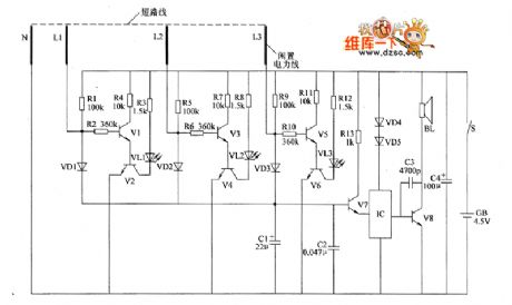
The agricultural irrigation line burglar alarm circuit is composed of the detection circuit and sound alarm circuit, and the circuit is shown as the chart. Detection circuit consists of resistors R1 ~ R12, LEDs VL1 ~ VL3, transistors VI ~ V6. Sound alarm circuit is composed of the diodes VD1 ~ VD3, transistors V7, V8, capacitors C1 ~ C3, resistor R13, audio integrated circuit IC and speaker BL. R1 ~ R13 select 1/4W metal film resistors or carbon film resistors. C1 and C4 select the aluminum electrolytic capacitors with the voltage in 10V; C2 uses the monolithic capacitor or polyester capacitor.
(View)
View full Circuit Diagram | Comments | Reading(759)
Agricultural irrigation controller circuit diagram 2
Published:2011/6/16 3:36:00 Author:Lucas | Keyword: Agricultural , irrigation controller
The agricultural irrigation controller circuit is composed of the power circuit, water level detection control circuit and control implementation circuit, and the circuit is shown as the chart. The power supply circuit is composed of the step-down capacitor C1, discharge resistor RI, rectifier diodes VD1, VD2, voltage regulator diode VS and filter capacitor C2. Water level detection control circuit is composed of the water level detection electrodes a, b, resistors R2 ~ R4, electronic integrated circuit and opto-coupler switch VLC. R1 selects 1/2W metal film resistor; R2 ~ R5 select l/4W metal film resistors or carbon film resistors.
(View)
View full Circuit Diagram | Comments | Reading(1357)
Intermittent power controller circuit diagram 7
Published:2011/6/16 4:07:00 Author:Lucas | Keyword: Intermittent , power controller
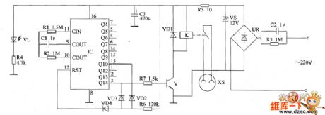
The intermittent power control circuit is composed of the power supply circuit, timer and control implementation circuit, and the circuit is shown as the Figure. The power supply circuit is composed of the step-down capacitor C2, discharge resistor R3, bridge rectifier UR, voltage regulator diode VS, current limiting resistors R4, R5, filter capacitor C3 and power indicator light-emitting diode VL. The timer circuit consists of counts / divider integrated circuit IC and resistors R1, R2, R6, capacitor C1 and diodes VD2 ~ VD4 . In the circuit, the R1, R2, C1 and the internal IC circuit form the clock oscillator circuit.
(View)
View full Circuit Diagram | Comments | Reading(540)
Intermittent power controller circuit diagram 6
Published:2011/6/16 4:04:00 Author:Lucas | Keyword: Intermittent , power controller
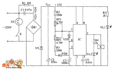
The intermittent power control circuit is composed of the power supply circuit and timing control circuit, and the circuit is shown as the Figure. The power supply circuit is composed of the step-down capacitor C1, resistors R1, R5, rectifier diodes VD1 ~ VD4, voltage regulator diode VS, power indicator LED VL1 and filter capacitor C2. Timing control circuit consists of the time-base integrated circuit IC, resistors R2 ~ R4, capacitors C3, C4, potentiometers RP1, RP2, diodes VD5, VD6, light-emitting diode VL2 and relay K. R2 ~ R5 use 1/4W carbon film resistors or metal film resistors.
(View)
View full Circuit Diagram | Comments | Reading(601)
Drainage and irrigation station centralized controller circuit diagram 2
Published:2011/6/18 21:14:00 Author:Lucas | Keyword: Drainage , irrigation , station, centralized controller
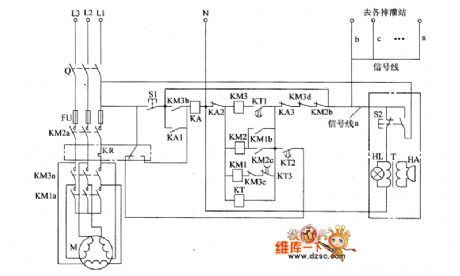
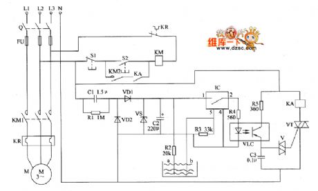
The drainage and irrigation station centralized controller circuit consists of the motor M, knife switch Q, fuse FU, AC contactors KMI ~ KM3, time relay KT, intermediate relay KA, thermal relay KR, control buttons S1, S2, signal line indicator Light HL, transformer T and buzzer HA etc., and the circuit is shown in the chart. S2 and HL, T, HA form the sound and light alarm circuit which is installed in the control room , and it connects with other irrigation and drainage stations through the signal lines a ~ n, and it can remote centralized control other pump motors by S2. KA chooses the JZC-22 AC relay. KT selects the JSD-8F time relay.
(View)
View full Circuit Diagram | Comments | Reading(615)
Drainage and irrigation station centralized controller circuit diagram 1
Published:2011/6/18 21:21:00 Author:Lucas | Keyword: Drainage, irrigation, station, centralized controller
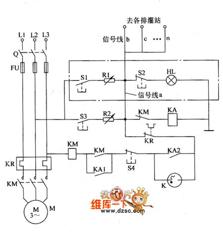
The drainage and irrigation station centralized controller circuit consists of the knife switch Q, fuse FU, start buttons S1, S3, stop buttons S2, S4, intermediate relay KA, AC contactor KM, thermal relay KR, fluorescent starter Κ, resistors RI, R2 and light HL, and the circuit is shown in the chart. S1, R1, S2, and HL form the control and instruction circuit which is installed in the control room, and each irrigation station has a signal line connected to the circuit. RI and R2 select the 300 ~ 1000Ω, 2 ~ 3W wire wound variable resistors. S1 and S3 use 380V, 5A press-pressure making buttons; S2 and S4 use 380V, 5A press-pressure moving off buttons.
(View)
View full Circuit Diagram | Comments | Reading(655)
Automatic sprinkler controller circuit diagram 8
Published:2011/6/18 22:21:00 Author:Lucas | Keyword: Automatic , sprinkler controller
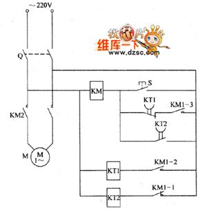
The automatic sprinkler controller circuit consists of the power switch Q, control button S, AC contactor KM, relays KT1, KT2, and the circuit is shown in the chart. KT1 and KT2 select the JS14S time relay. KM uses 220Y, 10A AC contactor, such as CDC10 series. KT1 gets power and works after KM1-2 closing. When the delay time set by KT1 arrives, the normally closed contacts disconnect in the delay time, then KM loses power and releases, and M stops working. At the same time, the normally closed contacts of KM are connected, then KT2 will begin to work. The above process taking place in a cycle can realize automatically timing sprinkler.
(View)
View full Circuit Diagram | Comments | Reading(730)
Automatic sprinkler controller circuit diagram 7
Published:2011/6/18 22:15:00 Author:Lucas | Keyword: Automatic , sprinkler controller
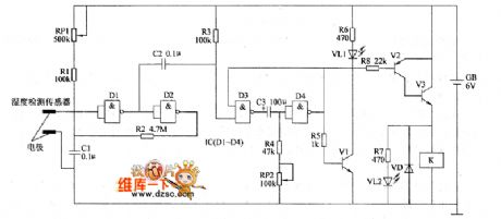
The automatic sprinkler controller circuit consists of soil moisture detection sensor, Schmitt trigger, monostable flip-flop, LED display circuit and control implementation circuit, and the circuit is shown in the chart. Schmitt trigger is composed of the Dl, D2 which are inside of the four NAND gate integrated circuit IC (Dl ~ D4) and resistors R1, R2, capacitors Cl, C2, potentiometer RP1. Monostable flip-flop is composed of the D3 D4 which are inside of IC, resistors R3, R4, potentiometer RP2 and capacitor C3. LED display circuit consists of transistor V3, light-emitting diodes VLI, VL2, and resistor R5 ~ R7. Control implementation circuit consists of the resistor R8, transistors VI, V2, relay K and diode VD. (View)
View full Circuit Diagram | Comments | Reading(1320)
Automatic sprinkler controller circuit diagram 6
Published:2011/6/18 22:04:00 Author:Lucas | Keyword: Automatic, sprinkler controller

The automatic sprinkler controller circuit is composed of the power supply circuit and humidity detection control circuit, and the circuit is shown in the chart. Power supply circuit is composed of the power transformer T, bridge rectifier UR, isolation diode VD2, zener diode VS and filter capacitors C1, C2 and so on. Humidity detection control circuit consists of the humidity sensor, the transistors V1 ~ V3, resistors R1 ~ R5, diode VDI and relay K. RI, R3 ~ R5 select l/4W carbon film resistors; R2 uses sealed variable resistor. C1 and C2 select the aluminum electrolytic capacitors with the voltage in 16V. VD1 uses the IN4007 silicon rectifier diode; VD2 uses the lN5401 silicon rectifier diode.
(View)
View full Circuit Diagram | Comments | Reading(1107)
Double control light switch circuit
Published:2011/6/28 18:50:00 Author:TaoXi | Keyword: Double control, light switch
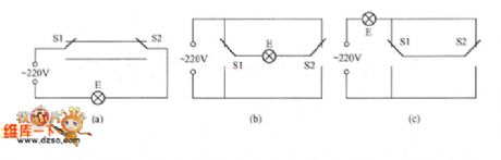
The double control switch is also called the ganged switch, it can be used in two different places such as the lower and upper stairs or the two ends of the aisle, it can independently control the turn-on or turn-off of the same light. The three connections are as shown in the figure, the S1 and S2 are the 1×2 SPDT switches, they can independently control the turn-on or turn-off of the light E. The connection of figure (b) shows that every switch has the phase line and the zero line of the power supply, so it is easy to install, but you need to pay more attention on the phase line and the zero line's short circuit when you are maintaining it.
(View)
View full Circuit Diagram | Comments | Reading(2086)
The Guangzhou-Honda rear fog lamp control circuit
Published:2011/6/28 20:43:00 Author:qqtang | Keyword: Guangzhou-Honda, rear fog lamp
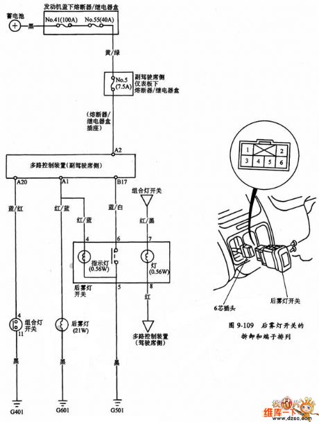
The Guangzhou-Honda rear fog lamp control circuit is shown in the figure.
(View)
View full Circuit Diagram | Comments | Reading(803)
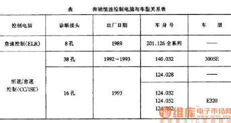
Benz constant speed control circuit
Published:2011/6/28 2:01:00 Author:Christina | Keyword: Benz, constant speed, control circuit
View full Circuit Diagram | Comments | Reading(502)
X-Y server control circuit
Published:2011/6/19 19:18:00 Author:TaoXi | Keyword: X-Y, server, control circuit
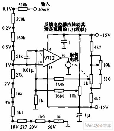
The X-Y server control circuit uses the MOSFET operational amplifier 9712 to drive the 10V, 0.2A servo motor. The servo motor can be used to confirm the position of the recording pen. The position control potentiometer has the coarse attenuation and the fine attenuation functions to the input signal. This circuit requires to use the very stable voltage-stabilized power supply.
(View)
View full Circuit Diagram | Comments | Reading(1154)
Stepping type servo control circuit
Published:2011/6/19 19:34:00 Author:TaoXi | Keyword: Stepping type, servo, control circuit
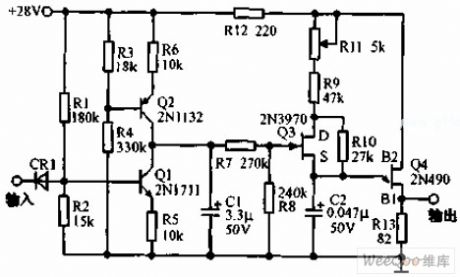
The stepping type servo control circuit is as shown in the figure, this circuit uses the changeable unijunction transistor (UJT) oscillator, in the control of the digital level, this oscillator produces the pulse sequence. When the logic level is 1, the oscillator produces 1000 pulses per second; when the logic level is 0, the oscillator produces 4400 pulses per second. When the logic level changes, the transition between the two pulse rate is smooth. The pulse sequence is used to start the stepping type servo motor. Q1 and Q2 are two constant current source, Q3 can be used as the voltage control resistance, it is in the parallel connection with R10 to control the pulse speed of the unijunction transistor (UJT) oscillator.
(View)
View full Circuit Diagram | Comments | Reading(701)
Remote control switch circuit with the infrared receiving decoding circuit
Published:2011/6/19 20:02:00 Author:TaoXi | Keyword: Remote control, switch, infrared, receiving, decoding
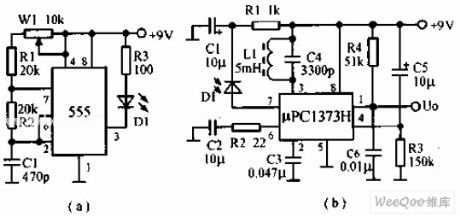
The infrared remote control switch circuit which uses the infrared receiving and decoding remote control circuit is as shown in the figure, the transmission circuit is composed of the astable multivibrator (composed of the 555). The oscillation frequency is about 38 kHz. The receiving circuit uses the special infrared receiving and decoding integrated circuit μPC1373H, the receiving circuit has the automatic brightness control circuit (ARC), so it has the accurate response to the infrared signals which have the different intensities and same frequencies. At this time, the output port has the low level to control the executive circuit.
(View)
View full Circuit Diagram | Comments | Reading(596)
Sound control infrared remote control switch circuit
Published:2011/6/19 20:16:00 Author:TaoXi | Keyword: Sound control, infrared remote control, switch circuit
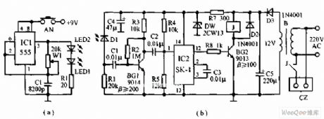
The infrared remote control switch circuit which uses the sound control circuit BH-SK-I is as shown in the figure, the generator is the multivibrator which is composed of the 555, the output pulse drives the infrared emission diode to output the infrared pulse signal. The receing tube matches the transmitting tube, it changes the infrared pulse into the electrical signal, and this electrical signal is amplified by the BG1 to trigger the IC2 sound control integrated circuit BH-SK-I. After triggered by the BG1, the pin-12 outputs the high level to make the BG2 to conduct, and the relay closes, the socket CZ gets power. If you want to close the machine, you just need to press the button AN, the IC2's internal trigger turns to output the low level, the BG2 cuts off, the relay releases, the socket loss the electricity.
(View)
View full Circuit Diagram | Comments | Reading(873)
Infrared remote control switch circuit with the PLL audio decoding circuit
Published:2011/6/19 20:33:00 Author:TaoXi | Keyword: Infrared remote control, PLL, audio decoding
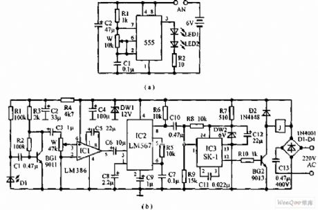
The infrared remote control switch circuit which uses the PLL audio decoding circuit is as shown in the figure, the emitter uses the multivibrator which is composed of the 555, the oscillation frequency is 1kHz to 20kHz. The receiver is composed of the infrared receiving amplifier, the audio decoder circuit and the sonic executive circuit. The infrared receiving tube needs to use with the transmitting tube. The infrared receiving amplifier is composed of the BG1 and IC1, the audio code circuit uses the audio code integrated circuit LM567 which has the phase locked loop, it requires the input signal not less than 25mV when this device is decoding, so we use the integrated power amplifier LM386 to get enough gain. The center frequency of LM567 is decided by the R5 and C7.
(View)
View full Circuit Diagram | Comments | Reading(1656)
Differential analog switch circuit
Published:2011/6/19 21:07:00 Author:TaoXi | Keyword: Differential, analog switch
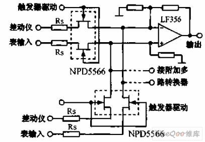
The differential analog switch circuit JFET components have the tracking capability that is better than 1% in the wide temperature range. The NPD5566 dual-JFET supplies the high-accuracy signal to the differential multiplexer to reduce the deviation which is caused by the common-mode signal. The resistance value depends on the operational amplifier and the application circuit.
(View)
View full Circuit Diagram | Comments | Reading(1176)
Ultra low leakage current multi-channel simulator circuit
Published:2011/6/19 21:23:00 Author:TaoXi | Keyword: Ultra low leakage current, multi-channel simulator
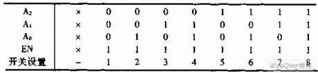
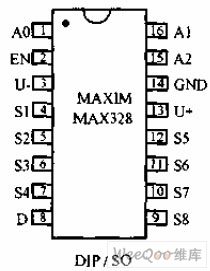
The ultra low leakage current multi-channel simulator circuit MAX328 is designed as one kind of 8-choose-1 analog switch. The three logic control ports and an enable port can be used to form the 16-choose-1 circuit. The switching time is less than 1.5μs. When you are using, every input port is connected with the 1/2W40KΩ resistance, this can make the MAX328 to bear the 110V AC voltage. The single power supply voltage is +10 to +30V, the single power supply operating voltage is +10 to +30V, the double power supply operating voltage is ±5V±18V. The package diagram and the true value table is as shown:
(View)
View full Circuit Diagram | Comments | Reading(545)
| Pages:237/312 At 20221222223224225226227228229230231232233234235236237238239240Under 20 |
Circuit Categories
power supply circuit
Amplifier Circuit
Basic Circuit
LED and Light Circuit
Sensor Circuit
Signal Processing
Electrical Equipment Circuit
Control Circuit
Remote Control Circuit
A/D-D/A Converter Circuit
Audio Circuit
Measuring and Test Circuit
Communication Circuit
Computer-Related Circuit
555 Circuit
Automotive Circuit
Repairing Circuit