
Control Circuit
Index 233
The high-power dual-way controllable dimmer circuit triggered by Ne lamps
Published:2011/6/29 4:52:00 Author:Seven | Keyword: high-power, dual-way, controllable dimmer
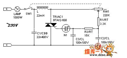
The high-power dual-way controllable dimmer circuit triggered by Ne lamps
(View)
View full Circuit Diagram | Comments | Reading(1867)
The auto controller circuit of toilet lights and ventilators
Published:2011/6/29 6:12:00 Author:Seven | Keyword: auto controller circuit, toilet lights
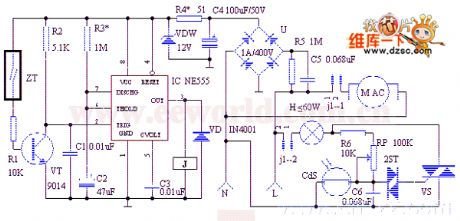
Working principles The working principles is shown in the figure, which consists of the magnet switch circuit, single steady time delay circuit, light lamp control circuit, ventilator control circuit and power supply circuit, etc. When the toilet is closed, the permanent magnet ZT is near the normally closed reed pipe AG, due to the magnet effect of ZT, the internal touch chip of AC is broken down, and the triode VT is blocked without the bias current, at the moment, the time-based integrated circuit IC1 2-pin is in a high LEV, so IC1 is in a reset state, and 3-pin if IC1 is outputting a low LEV.
(View)
View full Circuit Diagram | Comments | Reading(862)
Gas leak alarm circuit diagram
Published:2011/6/13 5:04:00 Author:Lucas | Keyword: Gas leak alarm
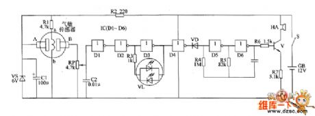
The gas leak alarm circuit is composed of the power supply circuit, gas detection circuit, LED indicating circuit and sound alarm circuit, and the circuit is shown as the chart. Power supply circuit is composed of the battery CB, power switch s, current limiting resistor R2, zener diode VS and filter capacitor C1. Gas detection circuit consists of the gas sensor, resistors R1 and potentiometer RP. LED indicating circuit consists of the NOT gates D1~D2 which are inside of NOT gate integrated circuit IC1(D1~D6), resistor R3, capacitor C2, and two-color light-emitting diodes VL. Sound alarm circuit is composed of the diode VD, NOT gates D4~D6 which are inside of IC, resistors R4 ~ R7, capacitor C3, transistor V, and buzzer HA. R2 uses 1/2W metal film resistor.
(View)
View full Circuit Diagram | Comments | Reading(1629)
Patients SOS Alarm (3)
Published:2011/6/28 6:25:00 Author:Sue | Keyword: Patients, SOS, Alarm
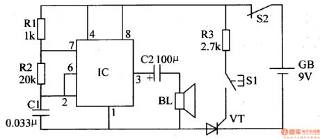
S2 is nomally closed power switch. When the madicine box is closed, the switch is connected. When the medicine box is open, S2 is disconnected.
When S is pushed, VT is disconnected. The oscillator doesn't work and BL makes no sound. When the patient pushes S1, the +9v voltage will be put on VT through S2 R3, which will make VT connected and the oscillator will begin to work. IC's pin 3 will output oscillate signals with a frequency of 1kHz. BL will make an alarm sound. When the medicine box is open, S is disconnected and VT is disconnected. BL will stops making sound. (View)
View full Circuit Diagram | Comments | Reading(990)
Patients SOS Alarm (2)
Published:2011/6/28 6:11:00 Author:Sue | Keyword: Patients, SOS, Alarm
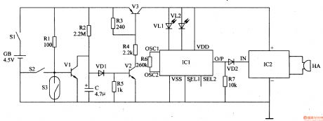
When there is no danger, S1 and S2 are connected. S3 is disconnected. V1 is connected while V2 and V3 are disconnected. IC2 IC3 don't work. HA makes no sound and VL1 VL2 are not illuminated.
When the patient fell on the ground because of the illness, S3 is connected and V1 is disconnected. V2 V3 are connected and IC1 IC2 begin to work. HA makes analarmsound. VL1 VL2 are illuminated and the characters Medical Aid and Medicine in the box will be seen on the rescue apparatus panel. (View)
View full Circuit Diagram | Comments | Reading(692)
Patients SOS Alarm (1)
Published:2011/6/28 6:00:00 Author:Sue | Keyword: Patients, SOS, Alarm
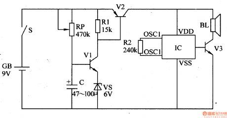
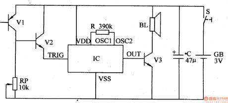
When there is no danger case, the alarm is in the pocket of the patient. S is disconnected. V1,V2 are disconnected. IC and BL do not work.
When the patient fell on the ground because of his illness, S is connected. C is charged by RP. When C's voltage reaches a certain value, V1 and V2 are connected. IC begins to work. The signal it outputs will promote BL to make an alarm sound after the signal is amplified by V3. (View)
View full Circuit Diagram | Comments | Reading(685)
Water-Infused Meat Detecting Alarm (4)
Published:2011/6/29 7:07:00 Author:Sue | Keyword: Water-Infused, Meat, Detecting, Alarm
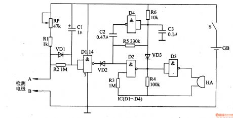
When the meat is detected, and if the meat is water-infused meat, the value resistance between the two electrodes will be large and D1 will input high level while output low level. VD2 is connected and the oscillator doesn't work. HA makes no sound. If the meat is water-infused meat, the resistance value will be small and D1 will input low level and output high level. VD2 is disconnected. The oscillator begins to work and HA will make an alarm sound. (View)
View full Circuit Diagram | Comments | Reading(704)
Water-Infused Meat Detecting Alarm (3)
Published:2011/6/29 7:00:00 Author:Sue | Keyword: Water-Infused, Meat, Detecting, Alarm
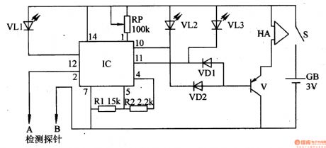
When pin 2 inputs high level, pin 11 and pin 12 will output high level while pin 10 will output low level. When pin 2 is input low level, pin 11 will output low level while pin 10 and pin 12 will output high level. When pin 2's voltage is between the high level and the low level, pin 10 and pin 11 will output high level while pin 12 will output low level.
When the meat is detected and if the meat is not water-infused meat, IC's pin 2 will have a volage between high level and low level. Pin 12 will output low level and VL1 is illuminated. V is disconnected and HA makes no sound.
If the meat has little water, IC's pin 2 will high a high level while its pin 10 will have a low level. VL3 is illuminated and HA will make an alarm sound. (View)
View full Circuit Diagram | Comments | Reading(715)
Water-Infused Meat Detecting Alarm (2)
Published:2011/6/29 6:54:00 Author:Sue | Keyword: Water-Infused, Meat, Detecting, Alarm
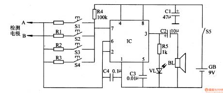
IC, R4, C4 and the detected meat will constitute an oscillator and the oscillate frequency is related to the water amount in the water. When the meat is detected, stick the electrodes into the detected meat. Push S1, and the oscillator will begin to work. VL begins to twinkling. BL makes an alarm sound. The more water the meat has, the smaller the resistance value will be and the higher the oscillate frequency will be. VL will have a larger twinkle frequency and BL will have a higher sound tone. (View)
View full Circuit Diagram | Comments | Reading(712)
Water-Infused Meat Detecting Alarm (1)
Published:2011/6/29 6:47:00 Author:Sue | Keyword: Water-Infused Meat, Detecting, Alarm
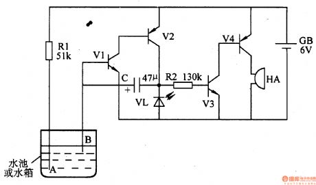
When S is pushed, stick the two electrodes into the meat. If the meat is not water-infused meat, the resistance value between A and B is large. V1 is disconnected. V2 is connected and V3 is disconnected. VL is not illuminated. BL makes no sound.
If the meat is water-infused meat, the resistance value between A and B will be smaller. V1 is connected and V2 is disconnected. V3 is connected. VL is illuminated and IC begins to work. BL will make an alarm sound after the signals are amplified by V4. (View)
View full Circuit Diagram | Comments | Reading(676)
Full Tank Alarm (2)
Published:2011/6/27 3:46:00 Author:Sue | Keyword: Full, Tank, Alarm
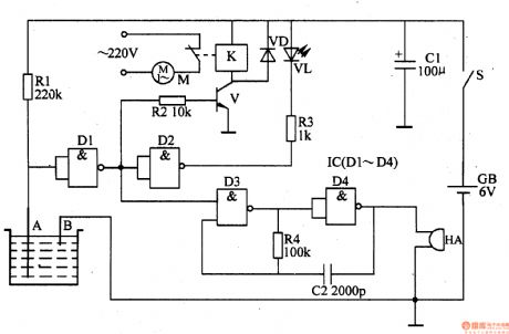
A and B are put in the tank as water level sensors. When the tank is not full, the resistance value between Aand B is large. D1's input terminal is high level while its output terminal is low level. V is disconnected. K is released. K's nornally closed interlock is connected. M begins to work. Then D2 outputs high level and VL is not illuminated. The oscillator composed of D3 D4 R4 C2 doesn't work and HA makes no sound.
When the water level reaches B, D1's input terminal is low level and its output terminal is high level. V is connected and K is connected. M stops working. Then D2 outputs low level, and VL is illuminated. The oscillator begins to work and HA makes an alarm sound. (View)
View full Circuit Diagram | Comments | Reading(1651)
Full Tank Alarm (1)
Published:2011/6/27 3:41:00 Author:Sue | Keyword: Full, Tank, Alarm
When the water level doesn't reach the set level, the resistance value between A and B is large. V1 is disconnected and the alarm circuit doesn't work. VL is not illuminated and HA doesn't make a sound.
When water reaches the set level, V1-V4 are connected and VL is illuminated. HA makes an alarm sound.
When the distance between A and B is changed, the alarm water level can be changed. (View)
View full Circuit Diagram | Comments | Reading(2859)
Boiling Water Alarm (3)
Published:2011/6/27 3:34:00 Author:Sue | Keyword: Boiling Water, Alarm
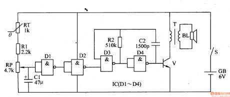
When S is on, attach RT to the kettle as a temperature sensor. When the temperature is low, RT has a high resistance value. D2 outputs low level and the oscillator and BL don't work.
As the temperature keeps going up, RT's resistance value is going down. When the water is boiled, D1 outputs low level. D2 outputs high level. The oscillator begins to work and the oscillate signal can promote BL to make an alarm sound after the signal is amplified by V. (View)
View full Circuit Diagram | Comments | Reading(765)
Boiling Water Alarm (2)
Published:2011/6/27 3:28:00 Author:Sue | Keyword: Boiling Water, Alarm
When the temperature in the kettle is low, VZ is disconnected and IC doesn't work. BL doesn't make a sound. As the temperature keeps going up, there is more lost current. When the water is boiled, the output voltage of V1 reaches the connect voltage value of V2, and V2 will be connected. IC will start to work. When the output sound signal is amplified by V3, BL will make an alarm sound. (View)
View full Circuit Diagram | Comments | Reading(845)
Boiling Water Alarm (1)
Published:2011/6/27 3:20:00 Author:Sue | Keyword: Boiling Water, Alarm
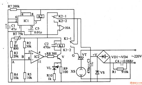
When the power is on, +V voltage will be put on IC2's pin 4, and will provide IC2 with working power. Then IC2's pin 5 has a higher voltage than pin 6. IC's pin 7 will output high level which will make V connected. VL is illuminated. K1 will work and make K1-2 connected. VT is triggered to connected and the electric kettle will begin to work.
As the temperature is going up, RT's resistance value is going down. When the temperature reaches 100℃, IC2's pin 6 has a higher voltage than pin 5 and pin 7 will output low level which will make V disconnected. VT is disconnected and the kettle stops working. When V is disconnected, VL is off.
When C1 finishes charging, IC1's pin 2 turns to high level and pin 3 outputs low level. K2-2 is connected and HA makes an alarm sound to indicate that the water is boiling. (View)
View full Circuit Diagram | Comments | Reading(770)
Domestic Seismic Alarm (4)
Published:2011/6/27 3:12:00 Author:Sue | Keyword: Domestic, Seismic, Alarm
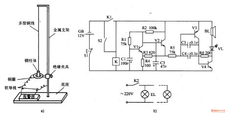
When there is no earthquake,S2 is disconnected and K is not connected. The audio oscillator and low frequent oscillator don't work. BL doesn't make a sound and VL and BLare not illuminated.
When there is an earthquake, S2 is connected and K is connected. The oscillators begin to work. BL makes an alarm sound and VL will twinkle with the alarm sound. At the same time, K2 will illuminated EL.
When S1 is pushed, the alarm can be canceled. (View)
View full Circuit Diagram | Comments | Reading(2296)
Domestic Seismic Alarm (3)
Published:2011/6/27 2:55:00 Author:Sue | Keyword: Domestic, Seismic, Alarm
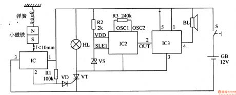
When the switch is on, the seismic alarm isin detection condition. When there is no earthquake, IC1's pin 3 outputs low level and VT is disconnected. The alarm circuit does not work.
When there is an earthquake, the magnet will move vertically. When it is away from IC1, IC1's pin 3 outputs high level and VT is connected. HL is illuminated. IC2 and IC3 begin to work. When the sound signal output by IC2 is amplified by IC3, BL will make an alarm sound. (View)
View full Circuit Diagram | Comments | Reading(2052)
Domestic Seismic Alarm (2)
Published:2011/6/27 2:51:00 Author:Sue | Keyword: Domestic, Seismic, Alarm

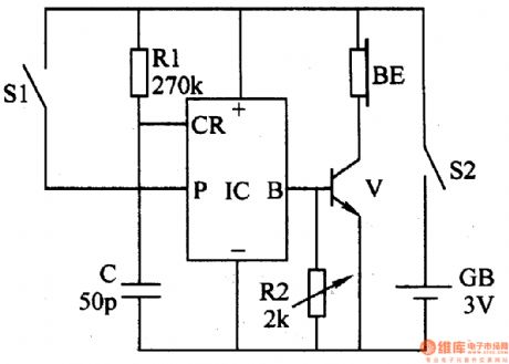
When to use the alarm, put it on the wall or on the window frame, and the distance between C and the little magnet should be within 3mm. When there is an earthquake, the magnet will be pushed. When the push force reaches a certain level, the magnet will move vertically which will make IC's pin 2 output high level. VT is connected and HA will make an alarm sound like DU DU . VL is illuminated. (View)
View full Circuit Diagram | Comments | Reading(985)
Domestic Seismic Alarm (1)
Published:2011/6/27 2:47:00 Author:Sue | Keyword: Domestic, Seismic, Alarm
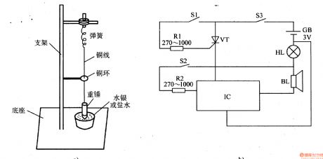
When to use the alarm, put it on the wall or on the window sill. When there is an earthquake, the heavy hammer will have vertical vibration. S1 is connected and VT is connected. IC begins to work, and BL will make a short alarm sound. At the same time, HL is illuminated. Then the heavy hammer will have horizontal mobility. When S2 is connected, IC is triggered and the alarm sound will be changed. (View)
View full Circuit Diagram | Comments | Reading(1884)
Anti Lost Alarm (4)
Published:2011/6/29 6:33:00 Author:Sue | Keyword: Anti Lost, Alarm
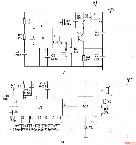
After the low-frequency oscillator begins to work, it will output 1kHz oscillate signals which will be output by W1.
When the distance between the receiver and the transmitter is within 3m, W2 will receive the high-frequency signals. IC2's pin 2 will output low level and IC3 doesn't work. BL makes no sound.
When the diatance is beyond 3m, the receiver receives no signals and IC2's pin 2 will output high level and IC3 begins to work. The signals will promote BL to make an alarm sound after the signals are amplified by V2. (View)
View full Circuit Diagram | Comments | Reading(1604)
| Pages:233/312 At 20221222223224225226227228229230231232233234235236237238239240Under 20 |
Circuit Categories
power supply circuit
Amplifier Circuit
Basic Circuit
LED and Light Circuit
Sensor Circuit
Signal Processing
Electrical Equipment Circuit
Control Circuit
Remote Control Circuit
A/D-D/A Converter Circuit
Audio Circuit
Measuring and Test Circuit
Communication Circuit
Computer-Related Circuit
555 Circuit
Automotive Circuit
Repairing Circuit