
Control Circuit
Index 241
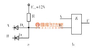
TTL integrated door circuit
Published:2011/6/16 1:10:00 Author:chopper | Keyword: TTL, integrated door
View full Circuit Diagram | Comments | Reading(585)
CMOS system power supply interface-DC switch circuit
Published:2011/6/20 19:13:00 Author:TaoXi | Keyword: CMOS, system, power supply, interface, DC, switch
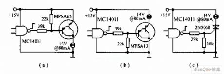
The CMOS system power supply interface-DC switch is as shown in the figure. Circuit (a) is the CMOS output circuit, it turns on and turns off the 14V, 80mA bulb circuit by using the small power transistor PNP Darlington MPSA65; circuit (b) uses the NPN Darlington MPAS13 high level to turn on the bulb; circuit (c) uses the CMOS output to drive the high sensitivity SCR 2N5060 directly. The high sensitivity SCR 2N5060 can be used in the extremely hard condition (-65℃), the maximum gate current is 35μA. It requires the CMOS to output the high level of 14.8V.
(View)
View full Circuit Diagram | Comments | Reading(1209)
IQS2404 button touch induction switch circuit
Published:2011/6/20 19:14:00 Author:TaoXi | Keyword: button, touch induction, switch
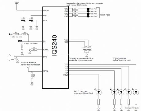
The IQS2404 button touch induction switch circuit (View)
View full Circuit Diagram | Comments | Reading(646)
CRT over-voltage protection circuit
Published:2011/6/20 21:46:00 Author:TaoXi | Keyword: CRT, over-voltage, protection
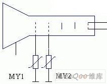
Because the distance between the poles of the CRT is very small, and also because some reasons of the production process, so if we add the ten thousand volt high voltage on the CRT's anode, there will be the jump-fire phenomenon between the anode and the other electrodes. In order to eliminate this phenomenon, some TVs install the disrharge tube on the CRT or use the metal clearance mode, but the two methods have poor reliability, if we use the ZnO voltage sensitive resistance, the effect will be good.
(View)
View full Circuit Diagram | Comments | Reading(595)
AC voltage stabilizer over-voltage and lightning protection circuit
Published:2011/6/20 21:54:00 Author:TaoXi | Keyword: AC, voltage stabilizer, over-voltage, lightning, protection circuit
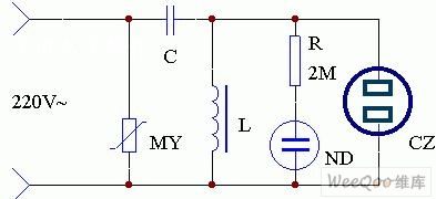
The application circuit of this device is as shown in the figure. Because the voltage of the rural power grid is not stabe, so we can make a simple AC magnetic saturation voltage device. The power input port of the AC voltage stabilizer is connected with a voltage sensitive resistance MY to prevent the impact of the TV set's overvoltage, and this makes the operating of TV more stable. If the AC voltage stabilizer works in the thunderstorm days, it has the lightning prevention function.
(View)
View full Circuit Diagram | Comments | Reading(1058)
Three-phase four-wire system power phase-lack protection circuit
Published:2011/6/20 22:16:00 Author:TaoXi | Keyword: Three-phase, four-wire, system, power, phase-lack, protection circuit
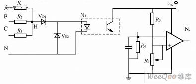
When the power supply is in the phase lack operating state, one limb of the rectifier bridge has no current, and other limbs will be damaged by the overcurrent, and the operating of inverter will be abnormal, so we must protect the phase lack. We usually use the current transformer or the electronic phase lack detection circuit to detect the phase lack of the power grid. Because the testing cost of the current transformer is high, and the volume is large, so we usually use the electronic phase lack detection circuit in the switch power supply. The simple electronic phase lack detection circuit is as shown in the figure. When the three-phase is balanced, the level of the R1~R3's node H is low, the light coupling output is near zero.
(View)
View full Circuit Diagram | Comments | Reading(761)
Relay closing indicating circuit
Published:2011/6/20 22:42:00 Author:TaoXi | Keyword: Relay, closing, indicating circuit
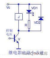
The relay is installed in the interior of the electrical equipment, the operating state is not intuitive, so the author makes some improvements which is as shown in the figure. The two ends of the coil are connected with the light-emitting diode VD1, when the control voltage is positive, the transistor conducts, the relay J closes, at the same time the light-emitting diode is turned on, this means the relay coil is coupled with the power. The light-emitting diode can be installed at the conspicuous place of the outer covering.
(View)
View full Circuit Diagram | Comments | Reading(620)
Relay driver circuit with the power voltage lower than the relay closing voltage
Published:2011/6/21 7:02:00 Author:TaoXi | Keyword: Relay, driver circuit, power voltage, relay closing voltage
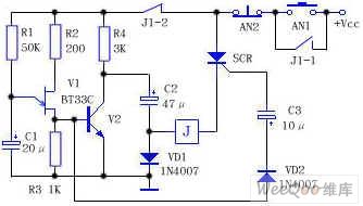
As the figure shows, the V1 is the single junction transistor BT33C, the relaxation type oscillator is composed of the R1, R2, R3 and C1, the SCR is the single-way SCR, after you press the button AN1, the circuit has the power, because the SCR has no trigger voltage, so it will not conduct, also the relay J will not work, the power supply charges the capacitance C2 to the power voltage through R4 and VD1 (Vcc-VD1 pressure drop). At the same time, the power supply charges the capacitance C1 through R1. After a few seconds, the voltage of C1 is charged to the trigger voltage of V1, so C1 discharges immediately through V1, a positive pulse is formed on R3 and this pulse adds to the base electrode of V2, so V2 conducts, the collector electrode of V2 (positive electrode of capacitance C2) is connected with the ground.
(View)
View full Circuit Diagram | Comments | Reading(663)
Multi-purpose electronic transformer circuit
Published:2011/6/21 21:05:00 Author:TaoXi | Keyword: Multi-purpose, electronic transformer

Here we introduce one kind of electronic transformer which belongs to the switch power supply family, and it is easy to make. After repeated experiments, we know the current response of this electronic transformer is very fast. It exceeds the ordinary operating frequency transformers, so this circuit can completely replace the power amplifier. The AC/DC electronic transformer has the over-current limit protection function, so it can be used to charge the electric bicycle's battery. If we connect some AC/DC electronic transformers in parallel, we can make the high power charger. Because this circuit has great current changing adaptability, so we can use it to replace the KW AC adapter of the sound power.
(View)
View full Circuit Diagram | Comments | Reading(5079)
Multi-tone alarm circuit
Published:2011/6/25 6:09:00 Author:TaoXi | Keyword: Multi-tone, alarm circuit
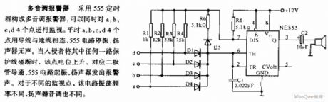
The multi-tone alarm circuit: the multi-tone alarm circuit is composed of the 555 timer, it can monitor the a, b, c, d points at the same time. In peacetime, the a, b, c, d points are connected with the ground line by wires, the 555 circuit stops working, the speaker is silent. When the invader touches off any one of the channels, the electric potential of this point will increase, the corresponding diode conducts, the 555 circuit starts oscillation, the speaker outputs the alarm. For different monitoring points, the oscillation frequencies are different too, and also the speaker tones.
(View)
View full Circuit Diagram | Comments | Reading(874)
Automatic floodlight circuit with the two-way thyristor
Published:2011/6/24 23:32:00 Author:TaoXi | Keyword: Automatic floodlight, two-way thyristor
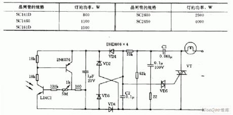
The circuit which uses the phototransistor as the illumination sensor is as shown in the figure. When the illumination is strong, the phototransistor and the L14C1 conduct. The diode VD3 conducts to make the voltage of capacitor C2 to zero, the two-way trigger tube VD5 and the two-way thyristor (triac) VT will not conduct, the light will not light. In the night, the L14C1 will not conduct, the voltage of C2 conducts the ST4 and VT, the light will turn on automaticly.
(View)
View full Circuit Diagram | Comments | Reading(626)
cinsisting of 555 single quantitative power supply controller circuit
Published:2011/6/20 8:57:00 Author:Fiona | Keyword: cinsisting of 555, single quantitative power supply controller
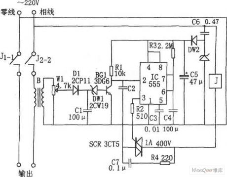
Load detection circuit is composed of the transformer B,D1,C1,W1 and it is used to measure circuit.Electronic switch is composed of the BG1,DW1 and R1 and it is controlled by testing signal.The regular time of the single stable circuit which is composed of the IC (555) and R3, C4 is td = 1.1R3C4,the parameters of the corresponding time is about four minutes. When the power exceeds the load,the voltage regulator tube DW1 is breakdown,BG1 saturated conducts,555 is set due to the potential of ② pin is low,the high level output by ③ pin makes the SCR conduct,relay J pulls in,contactor J1-1, J2-2 is off,cuts off ~ 220V power supply.
(View)
View full Circuit Diagram | Comments | Reading(621)
consisting of 555 the indoor humidity control circuit
Published:2011/6/20 8:57:00 Author:Fiona | Keyword: consisting of 555, the indoor humidity control
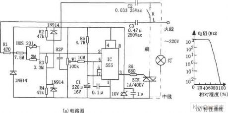
The controller is composed of step-down rectifier circuit,humidity sensor,single stable circuit,Silicon controlled control circuit and so on.Step-down rectifier circuit provides DC voltage VDD=+10V for the whole control circuit.Single stable circuit is composed of IC,wet sensitive network,R5,C1 and so on. When the humidity exceeds the predetermined value,555 ② pin potential is high,555 is reset,the low level output by ③ pin makes the SCR conduct,turns on exhaust fan power To do exhaust to reduce humidity.Emission time is determined by timing time constant R5C1 and the level of control terminals ⑤ pin.Adjust W1 be preset the emission time.
(View)
View full Circuit Diagram | Comments | Reading(2593)
consisiting of CH7555 program controller circuit
Published:2011/6/20 8:57:00 Author:Fiona | Keyword: consisiting of CH7555, program controller
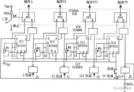
Figure shows the program control circuit.The controller is composed of recycling program,power trigger circuit and so on. 4 pieces 555 circuit IC1 ~ IC4 are composed of different timing monostable circuit and series cycle trigger.Power trigger is composed of the IC7 (CD4069) hex inverter,so that all single-circuits are regular stable set.C6 (CC4081) is four 2-input AND gate;IC5 (CC4044) is the four R. S latch.When you press the start button,IC1 is set and enters single state temporary stability state.That is the first program to run.
(View)
View full Circuit Diagram | Comments | Reading(585)
Consisting of 555 water and sewage control circuit
Published:2011/6/18 8:01:00 Author:Fiona | Keyword: consisting of 555, water and sewage control
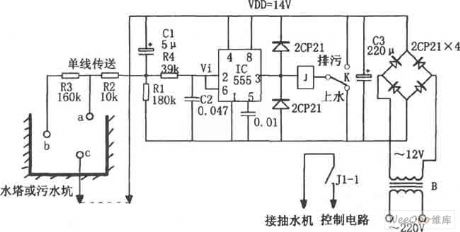
The controller consists of the step-down rectifier circuit,the water level probe (a, b, c),555 trigger,relay control circuit and so on.The step-down rectifier circuit provides DC voltage for the whole control circuit.When controller is used for water tower sheung shui,if the water level is below the point b,then 555 is set due to the ② pin potential is low level,the high level output by 3 pin makes the relay J close,contact J1-1 connects,pump starts to sheung shui. When the water level rises to a point,555 is set due to the ⑥ pin potential is higher than 2/3VDD,the low level output by 3 pin makes the relay J release,contact J1-1 is off,pump stops without electricity.So that the water level maintains a certain range.
(View)
View full Circuit Diagram | Comments | Reading(1476)
The protection circuit composed of the pressure sensitive resistor
Published:2011/6/13 20:12:00 Author:Christina | Keyword: protection circuit, pressure sensitive resistor
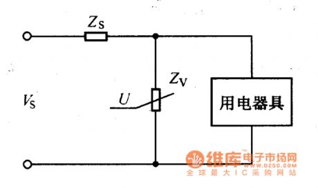
The pressure sensitive resistor is always connected with the input port of the protected electrical in the circuit, as the figure shows. From the figure we can see the voltage divider is composed of the pressure sensitive resistor's impedance zv and the circuit's total impedance, so the limit voltage of the pressure sensitive resistor can be determined by the formula: Vc=VsZv/(Zs+Zv)
VC--limit voltage;VS--surge voltage;ZV--the impedance of the pressure sensitive resistor;ZS--the total impedance of the circuit.
The formula shows that when the large current gets through the Zv, the transient overvoltage lands on it mostly, so the voltage of the protected electric equipment is lower than the limit voltage of it, so this circuit can play the protection function.
Figure The protection circuit composed of the pressure sensitive resistor (View)
View full Circuit Diagram | Comments | Reading(669)
H type of a brush type control circuit
Published:2011/6/20 9:13:00 Author:Fiona | Keyword: H type, a brush type control
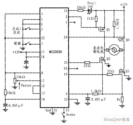
MC33035 can use the least amount of devices to control a brushless motor by driving an H electricity four bridge.The key of this control is:To code the input sensor into 100, meanwhile,when the controller forward / reverse pin is logic level 1,it should also produce the drive signal of top to left Q1 and button to right Q3, and when the forward / reverse pin is logic level,it should also produce the drive signal of top to right Q4 and button to left Q2.The code ensures that H-drive meets the direction and speed control requirements. The controller can work properly in about 25kHz PWM frequency.
(View)
View full Circuit Diagram | Comments | Reading(1167)
the op-amp analog switch with high anti-interference ability circuit
Published:2011/6/21 1:35:00 Author:Fiona | Keyword: the op-amp analog switch, high anti-interference ability
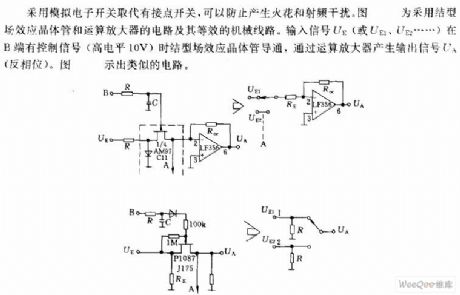
The circuit uses analog electronic switches to replace the node switch to prevent sparking and radio-frequency interference.The picture shows the circuit using junction field-effect transistor and operational amplifier and its equivalent mechanical lines.When the input signal UE (UE1, UE2) has control signal (high 10V) in the B side,the junction field-effect transistor conducts, produces the output signal UA through the operational amplifier. The picture is shown a similar circuit.
(View)
View full Circuit Diagram | Comments | Reading(1213)
BA8206 fan single chip microcomputer integrated circuit
Published:2011/6/13 20:47:00 Author:Christina | Keyword: fan, single chip, microcomputer, integrated circuit
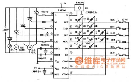
The BA8206 is designed as one kind of fan single chip microcomputer integrated circuit that is produced by the Toyo company, and it can be used in the program control system of various types of fan.
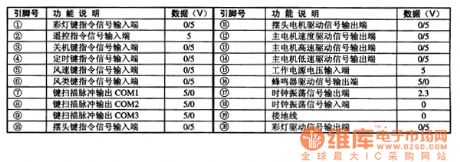
The BA8206 uses the 20-pin dual-row DIP package, the pin functions and data are as shown in table 1, the typical application circuit is as shown in figure 1. The operating voltage range of this IC is 3-5V, the quiescent current is 500μA, the SCR trigger output current is 10mA.
Table 1 The pin functions and data of the BA8206
Figure 1 The typical application circuit of theBA8206
(View)
View full Circuit Diagram | Comments | Reading(6369)
BA7101 infrared remote control transmitter integrated circuit
Published:2011/6/13 21:49:00 Author:Christina | Keyword: infrared remote control, transmitter, integrated circuit
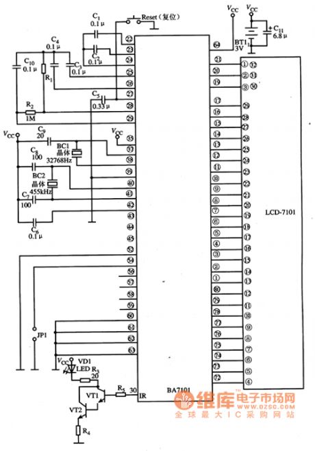
The BA7101 is designed as one kind of infrared remote control transmitter integrated circuit that is produced by the Toyo company, and it can be used in the remote controller of various brands of air conditioner remote control systems.
1.Features
The BA7101 is composed of the clock oscillation circuit, the reset circuit, the button pulse producing circuit, the button scanning instruction encoding circuit, the test circuit, the LCD displayer signal decoding drive circuit and other auxiliary function circuits.
2.Pin functions
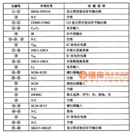
The BA7101 is in the 80-pin square flat package, the pin functions are as shown in table 1.
Table 1 The pin functions of the BA7101(80PINPQFP)
3.Typical application circuit
The LCD air conditioning which is composed of the BA7201 is as shown in figure 1.
Figure 1 The typical application circuit of the BA7201
(View)
View full Circuit Diagram | Comments | Reading(606)
| Pages:241/312 At 20241242243244245246247248249250251252253254255256257258259260Under 20 |
Circuit Categories
power supply circuit
Amplifier Circuit
Basic Circuit
LED and Light Circuit
Sensor Circuit
Signal Processing
Electrical Equipment Circuit
Control Circuit
Remote Control Circuit
A/D-D/A Converter Circuit
Audio Circuit
Measuring and Test Circuit
Communication Circuit
Computer-Related Circuit
555 Circuit
Automotive Circuit
Repairing Circuit