
Control Circuit
Index 245
Three-phase AC electric welder no-load automatic stop control circuit
Published:2011/6/22 19:09:00 Author:TaoXi | Keyword: Three-phase, AC, electric welder, no-load, automatic stop, control circuit
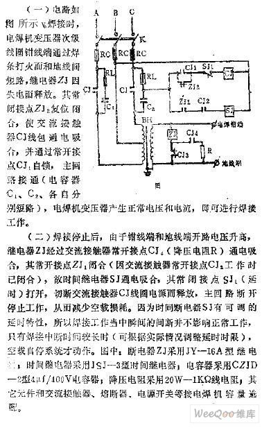
The circuit is as shown in the figure. The subprime coil clamp line port of the electric welder's transformer is connected with the landline through the welding rod to form the short circuit, the relay ZJ releases. The normally closed contact point ZJ2 closes to make the AC contactor CJ to close, and it locks itself through the normally open contact point CJ1, the major loop is connected, the electric welder's transformer produces the normal voltage and current, so you can do the welding work.
After the welding stops, because the open-circuit (composed of the clamp line port and the landline port) voltage increases, so the relay ZJ gets power to close through the AC contactor's normally open contact point CJ4.
(View)
View full Circuit Diagram | Comments | Reading(889)
Simple servo motor drive control circuit
Published:2011/6/23 2:07:00 Author:TaoXi | Keyword: Simple, servo motor, drive control
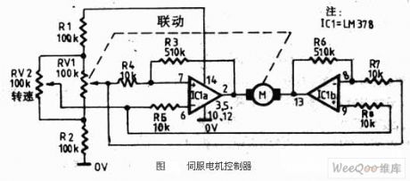
The servo motor is designed as one kind of traditional motor. It is the execution component of the automatic device. The most important feature of the servo motor is the controllable feature. When there is the control signal the servo motor turns, and the speed is proportional to the control voltage. If you remove the control voltage, the servo motor will immediately stop turning. The servo motor can be used in wide range of applications such as all of the automatic control system and the household electrical appliances (CD players, video players).
Figure: The simple servo motor drive control circuit (View)
View full Circuit Diagram | Comments | Reading(4988)
The Tianjin Chia Tai elevator control circuit
Published:2011/6/20 22:15:00 Author:Seven | Keyword: elevator control, Chia Tai
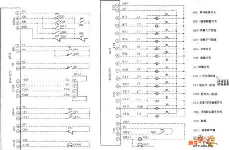
The Tianjin Chia Tai elevator control circuit is shown as above.
(View)
View full Circuit Diagram | Comments | Reading(1606)
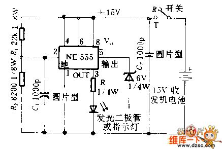
The motor integrated protection alarm circuit
Published:2011/6/22 4:13:00 Author:Borg | Keyword: integrated protection, alarm
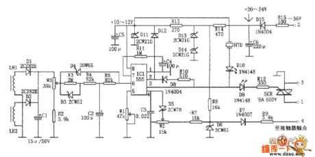
The integrated protection equipment fulfills the auto power failure protection of overload, phase breaking, short circuit and so on, and it can block the motor by limiting time between phase and ground of the motor or loading cable. The core of the equipment is the 555 time-base circuit, it makes full use of the features of 555 trigger offset, reset and control, such as using the prior reset feature of 4-pin as the input terminal of the leakage detection; using the high impedance threshold value feature of 6-pin, when there are failures of overload, phase breaking and short circuit, it is working as the reset terminal of over-current protection. (View)
View full Circuit Diagram | Comments | Reading(678)
The dual-way controllable silicon working principle circuit of the liquid level control
Published:2011/6/20 21:53:00 Author:Seven | Keyword: controllable silicon, working principle, liquid level control
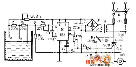
See as the figured circuit, the controller composed of the water level detector, trigger controller and step-down rectifier circuit, etc.
The bias circuit composed of water detecting poles of a, b, c, W1, R1,R2 and R3 is the level detector.When the level is under b, Vp-b≈R3×VDD/(Rw1+R1+R2+R3)<1/3VDD, 555 is offset, SCR is triggered and conducting, the motor runs and draws water.When the level is above a, Vp-a≈R3×VDD/(Rw1十R3)>2/3VDD, 555 is reset, 3-pin is in a low LEV. SCR is blocked and the motor stops running . (View)
View full Circuit Diagram | Comments | Reading(759)
The light dependent control circuit
Published:2011/6/20 22:21:00 Author:Seven | Keyword: light dependent, control circuit
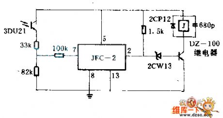
When one of the warps is broken, the light barrier which was hold by the warp is falling and blocks the light source of the LDR 3DU21, then the relay circuit is released, which controls the pulling over of the motor. The circuit is shown in the figure. (View)
View full Circuit Diagram | Comments | Reading(625)
Operational amplifier zero adjustment circuit
Published:2011/6/13 5:14:00 Author:Christina | Keyword: Operational amplifier, zero adjustment
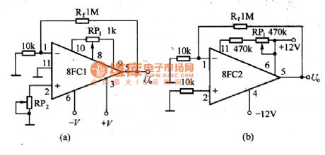
The common zero adjustment circuit is as shown in the figure.
The operational amplifier zero adjustment circuit
In figure (a), the potentiometer RP is connected with the internal input differential amplifier stage to change the voltage difference of the collector electrode, by this method, you can adjust the zero point; or you can connect the potentiometer RP2 with the input port of the integrated operational amplifier, let the bias current flow through the RP2 to cause the imbalance of the two input bias currents, so you can adjust the zero point.
For some pperational amplifiers with low drift and small input current, you can add a high resistance potentiometer to the collector electrode of the input amplifier stage according to the polarity of the partial zero to make the collector resistance imbalance to change the electric potential difference of the input stage, so the output is zero, as the figure (b) shows.
The auxiliaryzero adjustmentcircuit (View)
View full Circuit Diagram | Comments | Reading(1672)
CD4066 4-channel electronic switch integrated circuit
Published:2011/6/13 6:31:00 Author:Christina | Keyword: 4-channel, electronic switch, integrated circuit
The CD4066 is designed as one kind of 4-channel electronic switch integrated circuit that can be used in wide range of applications such as the TV, VCD, telephone and All kinds of electronic instrument meter.
1.Features
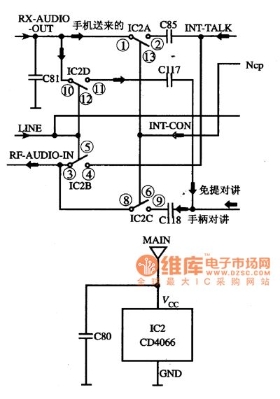
The CD4066 is mainly composed of four channels of electronic switch with the same functions, each electronic switch is controlled by the corresponding pin's input electrical level, the electrical level turns on or turns off the electronic switch. Their control pins are pin-13 (controls the pin-1 and pin-2), pin-5 (controls the pin-3 and pin-4), pin-6 (controls the pin-8 and pin-9), pin-12 (controls the pin-10 and pin-11).
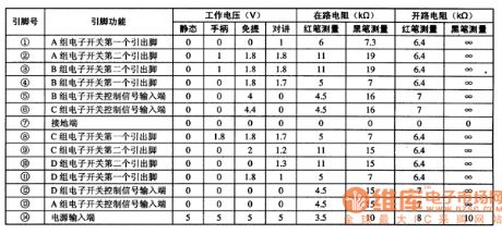
2.Pin functions and data
The CD4066 is in the 14-pin dual-row DIP package, the pin functions and application measured data of the cordless telephone is as shown in table 1.
Table 1 The CD4066's pin functions and application measured data of the cordless telephone
3.The typical application circuit
The CD4066's typical application circuit of the cordless telephone is as shown in figure 1.
Figure 1 The CD4066's typical application circuit of the cordless telephone
(View)
View full Circuit Diagram | Comments | Reading(2364)
27MHz crystal oscillator circuit
Published:2011/6/13 7:11:00 Author:Christina | Keyword: 27MHz, crystal oscillator
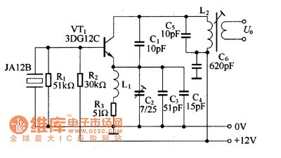
The 27MHz crystal oscillator circuit is as shown in the figure. The R1, R2, R3 are the biasing resistor, the C6 is the bypass capacitor, the voltage division circuit is composed of the C1, C3, C4 and C2 to control the oscillation strength. The L1 is the high-frequency choking coil which has the filtering effect.
The quartz crystal is in the parallel resonant state, the oscillation frequency of the oscillator depends on the natural frequency of quartz crystal. The L2 and C5 decide the oscillation strength.
Figure 15 The 27MHz crystal oscillator circuit
(View)
View full Circuit Diagram | Comments | Reading(4702)
OOK 315MHz Emitter Module Circuit Diagram
Published:2011/6/19 3:54:00 Author:Vicky | Keyword: OOK 315MHz Emitter Module
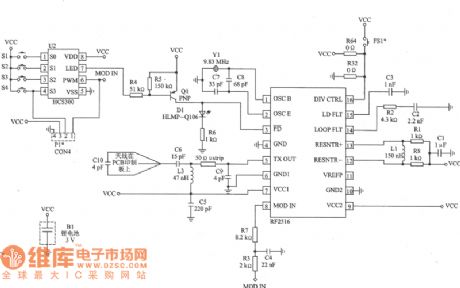
DKl000T is an emitter module composed by RF2516 and roll-code encoding device. Correspondingreceptor module is DKl000R. DKl000T is suitable to be applied in keyless-entering system, wireless safe system, remote monitoring and remote control.
Main technical features are listed as follows:
·Operating frequency: 315MHz;
·Modulation mode of 00K;
·Roll-code encoding;
·LED indicator;
·Output power: 70 dBμV/m 5;
·Voltage of power supply: 2~3 V ;
·Dissipation of current: 4~9 mA;
· Printing the antenna in the printing board.
Applied circuit of DKl000T module 315Hhz
(View)
View full Circuit Diagram | Comments | Reading(1349)
ASK/FSK 450~300MHz Emitter Circuit Diagram
Published:2011/6/18 10:42:00 Author:Vicky | Keyword: ASK/FSK 450~300MHz
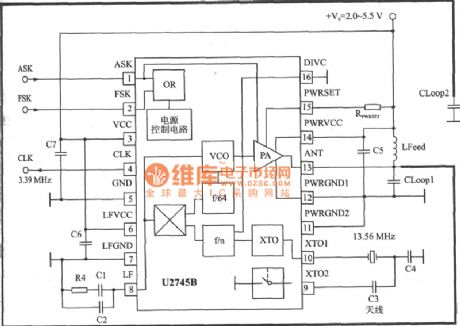
U27418 is a PLL emitter chip specially designed for meeting the low cost of data communication. The corresponding receiver chip is U3741.
Main technical features are listed as follows:
·Emitting frequency: 300~450 MHz;
·Modulation mode of ASK/FSK;
·Maximum transmission rate: 0 Kb/s;
·Voltage of power supply: 2.O~5.5 V;
·Maximum output power: 5 dBm(Vs=3 V,f=433.92 MHZ 9RPWRSET=1.2 kΩ);
·Maximum dissipation of power: 250 mW ;
·Maximum work current : l2.5 mA, maximum current of low-power mode: 0.35μA ;
·Microprocessor clock signal ,which can be compatible with microcontroller such as M44C090 and M44C890;
·ESD protection (excluding pins XT02 and XT01)as requested by MIL-STD.883(4KV HBM);
·Work temperature: -20~+70℃.
Applied circuit of U2741
(View)
View full Circuit Diagram | Comments | Reading(1748)
The sound frequency noise generator principle circuit
Published:2011/6/21 6:28:00 Author:qqtang | Keyword: sound frequency, noise generator
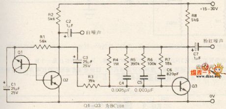
View full Circuit Diagram | Comments | Reading(612)
vehicle anti-theft device with ND vibration modules circuit
Published:2011/6/21 7:57:00 Author:John | Keyword: anti-theft device, vehicle, vibration module
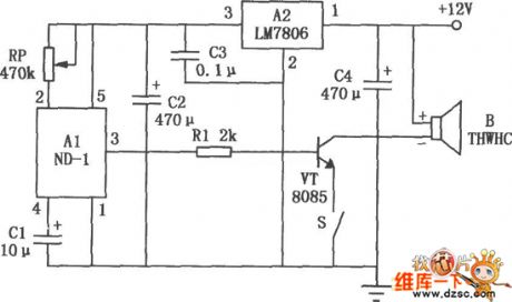
Sensing part is the most advanced solid-state acceleration detection device, which have high detection sensitivity to vibration and have inhibit function to the surrounding environment’s noise signals. It is with strong anti-interference ability. The device contains dedicated control chip inside. And it is easy to use. It can be used for directly driving small power loads or a relay or alarm after being through amplification circuit. Therefore, it is widely used for anti-theft device in motor vehicles, safes, warehouse doors and windows and other occasions.
(View)
View full Circuit Diagram | Comments | Reading(697)
Switching Constant-Current Application Circuit Composed Of W723
Published:2011/6/14 23:18:00 Author:Robert | Keyword: Switching, Constant-Current, Application
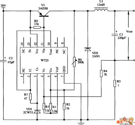
The picture shows the constant-current switching regulator application circuit composed of W723 multi-port adjustable positive regulator. Its output current is 1A. In the circuit in the picture, the R1, R2 would divide the W723's reference voltage (about 7.2V) to about 3V and then add it into the in-phase input port. Also the resistance R3, R4 would divide the reference voltage to add into the out-phase input port. The R4's low port is connected with the current-divider resistance R5. When the out-phase input and in-phase input are nearly balanced, the current-divider resistance R5's voltage drop would be about 1V. R6 is used to adjust the limiting value of output ripple current.
(View)
View full Circuit Diagram | Comments | Reading(1435)
The large power dual-way thyristor light regulator circuit used in 230v filament lamps
Published:2011/6/20 20:40:00 Author:Seven | Keyword: large power, light regulator, filament lamps
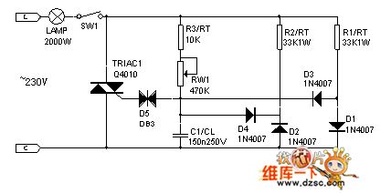
The large power dual-way thyristor light regulator circuit used in 230v filament lamps
(View)
View full Circuit Diagram | Comments | Reading(2476)
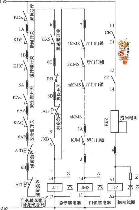
The Beijing Fiery elevator control circuit
Published:2011/6/20 22:16:00 Author:Seven | Keyword: Fiery, control circuit
The Beijing Fiery elevator control circuit is shown as above. (View)
View full Circuit Diagram | Comments | Reading(3537)
The gradient controller principle circuit
Published:2011/6/20 11:06:00 Author:Seven | Keyword: gradient controller
View full Circuit Diagram | Comments | Reading(670)
The data general control circuit
Published:2011/6/20 22:17:00 Author:Seven | Keyword: data, general control
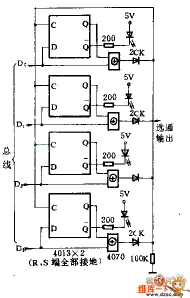
The data general control circuit is shown as above.
The circuit has functions of judging the change of the data, locating and outputting strobe pulses. Usually, the output of each OR gate is 0 , and the strobe output is also 0 . If either terminal changes its stage, the corresponding OR gate will output 1 immediately, the jumping is fed back to the clock terminal of the 4 D triggers, and the general state is located. Then, all the 4 OR gates output low LEV. (View)
View full Circuit Diagram | Comments | Reading(818)
The Beijing Tujie elevator control chamber circuit
Published:2011/6/20 9:15:00 Author:Seven | Keyword: elevator control chamber
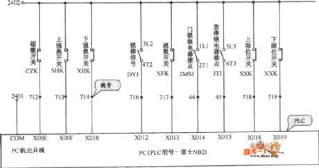
The Beijing Tujie elevator control chamber circuit is shown in the figure.
(View)
View full Circuit Diagram | Comments | Reading(599)
The Beijing Wuzhou elevator control chamber circuit
Published:2011/6/20 22:12:00 Author:Seven | Keyword: elevator, control chamber
The Beijing Wuzhou elevator control chamber circuit is shown as above:
(View)
View full Circuit Diagram | Comments | Reading(731)
| Pages:245/312 At 20241242243244245246247248249250251252253254255256257258259260Under 20 |
Circuit Categories
power supply circuit
Amplifier Circuit
Basic Circuit
LED and Light Circuit
Sensor Circuit
Signal Processing
Electrical Equipment Circuit
Control Circuit
Remote Control Circuit
A/D-D/A Converter Circuit
Audio Circuit
Measuring and Test Circuit
Communication Circuit
Computer-Related Circuit
555 Circuit
Automotive Circuit
Repairing Circuit