
Control Circuit
Index 259
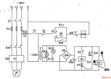
Motor protector circuit diagram 12
Published:2011/5/21 1:47:00 Author:Lucas | Keyword: Motor protector
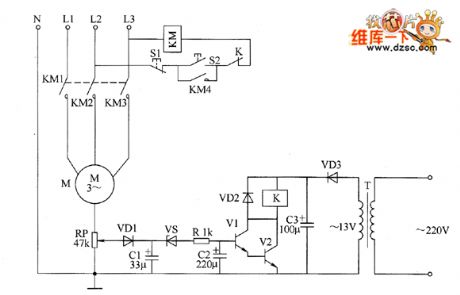
The motor protector circuit is composed of the power supply circuit and voltage detection control circuit, the circuit is shown as the chart. Power circuit is composed of the power transformer T, rectifier diode VD3 and filter capacitor C3. Voltage detection control circuit is composed of the potentiometer RP, diodes VD1, YD2, capacitors C1, C2, voltage regulator diode vs, resistor R, transistors V1, V2 and relays K. KM is the the original AC contactor in the motor control circuit, S1 and S2 are the stop button and start button respectively in the original motor control circuit of motor. AC 220V voltage is bucked by T, half-wave rectified by VD3 and filtered by C3 to provide DC operating power for K and its driving circuit.
(View)
View full Circuit Diagram | Comments | Reading(826)
touch switch delay circuit
Published:2011/5/24 0:13:00 Author:John | Keyword: touch switch
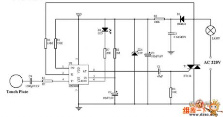
Touch switch delay circuit is shown below.
(View)
View full Circuit Diagram | Comments | Reading(2035)
Agricultural Automatic Water Feeder (4)
Published:2011/5/22 19:44:00 Author:Sue | Keyword: Agricultural Automatic Water Feeder
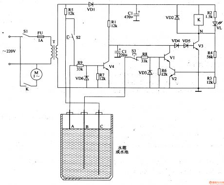
When there is no water, V1,V2,V4 are disconnected, and K is connected. M begins to feed water and VL is illuminated.
When the level reaches B, V1 has high level and V2 has low level. M continues to feed water.
When the level reaches A, V4 has high level. V3 is disconnected and K is released. VL goes out and M stops working.
When the level is lower than A, V4 is disconnected and V3 is disconnected. K and KM don’t work. When the level is lower than B, V1 V2 are disconnected and VL is illuminated. M begins to feed water. (View)
View full Circuit Diagram | Comments | Reading(834)
Agricultural Automatic Water Feeder (2)
Published:2011/5/22 19:34:00 Author:Sue | Keyword: Agricultural, Automatic, Water Feeder
When the level is low, VT is triggered to be connected and K1 is connected. HL2 is illuminated and M begins to feed water.
When the level is becoming higher, VT is still connected. When the level reaches a certain level, K2 is connected and K1 is released. VT is disconnected. HL2 goes out and M stops feeding water.
When the level is lower, K1 and KM are disconnected. When the level reaches SA1, VT is connected again and M begins to feed water again. (View)
View full Circuit Diagram | Comments | Reading(652)
switch delay circuit
Published:2011/5/20 5:29:00 Author:chopper | Keyword: switch delay
View full Circuit Diagram | Comments | Reading(659)
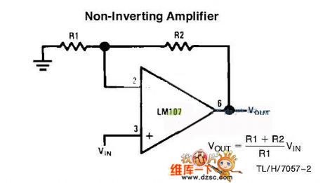
noninverting amplifier circuit
Published:2011/5/20 5:37:00 Author:chopper | Keyword: noninverting, amplifier
View full Circuit Diagram | Comments | Reading(650)
Agricultural Automatic Water Feeder (10)
Published:2011/5/22 20:19:00 Author:Sue | Keyword: Agricultural, Automatic, Water Feeder
When the level is lower than c, V1 V3 are disconnected and +12V voltage is put on V2, making V2 connected.K is connected and KM begins to work. M begins to feed water.
When the level reaches C, V3 has a low level and is connected. Its integrated electrode becomes low level. VD4 is disconnected and K1 is connected. M keeps on working.
When the level reaches b, V1 has a high level and is connected. Its integrated electrode becomes low level. V2 is disconnected and K is released. M stops working . When the level is lower than the lowest level, M begins to feed water again. (View)
View full Circuit Diagram | Comments | Reading(555)
Agricultural Automatic Water Feeder (9)
Published:2011/5/22 20:13:00 Author:Sue | Keyword: Agricultural, Automatic, Water Feeder
When the multivibrator begins to work, IC2's 3 pin outputs oscillator signals. When the level is lower than b, IC3's 2 pin has high level and 3 pin has low level. K is connected and K1 is connected. M begins to work. K's K2 is disconnected.
When the level is between a and b, but lower than c, K2 is disconnected and IC3's 2 pin has high level. M is still working. When the level is higher than c, IC2's 3 pin will output low level pulse, which will be put on to 2 pin. 3 pin becomes high level and K is released. K1 is disconnected and M stops working.
When the level is between a and b, K2 is disconnected and M doesn't work. When the level is lower than a,b, IC3's 2 pin becomes high level and 3 pin has low level. M begins to work again. (View)
View full Circuit Diagram | Comments | Reading(526)
Agricultural Automatic Water Feeder (8)
Published:2011/5/22 20:05:00 Author:Sue | Keyword: Agricultural, Automatic, Water Feeder

When S is on, IC's 2 pin and 6 pin have low level and 3 pin outputs high level. V2 is connected and K is connected. VL2 is illuminated. When C2 finishes charging, IC's 2 pin becomes high level, but its 6 pin is still low level. 3 pin is high level and YV is still working.
When the water tank is full, IC's 6 pin is low level and 3 pin has low level. V2 is disconnected and K is released. YV stops working and VL3 is illuminated. At the same time, V1 is connected and VL1 is illuminated, indicating that the water tank is full. (View)
View full Circuit Diagram | Comments | Reading(555)
Agricultural Automatic Water Feeder (7)
Published:2011/5/22 20:00:00 Author:Sue | Keyword: Agricultural Automatic Water Feeder
When the power is on and the level is lower than L, A’s level is highest and V1 V2 are connected. K is connected and K2 K1 are connected. M begins to feed water.
When the level is higher than H, A’s voltage is reduced to 0.2-0.3V.V1 and V 2 are disconnected. K is released and M stops working. When the level is lower than L, V1 and V2 are connected again and M begins to feed water again. (View)
View full Circuit Diagram | Comments | Reading(545)
Agricultural Automatic Water Feeder (6)
Published:2011/5/22 19:57:00 Author:Sue | Keyword: Agricultural, Automatic, Water Feeder
When there is little water, there is no current in the circuit. K is released and KM is connected. M begins to feedwater.
When the level reaches L, there is dc voltage in the circuit, and it will generate 12V voltage. V is disconnected and 3 pin has low level. M is still working.
When the level reaches H, V is connected and 3 pin outputs high level. K is connected and KM is disconnected. M stops working.
When the level is lower than L, the circuit is disconnected again. K is released and M begins to feed water again. (View)
View full Circuit Diagram | Comments | Reading(527)
Agricultural Automatic Water Feeder (5)
Published:2011/5/22 19:50:00 Author:Sue | Keyword: Agricultural, Automatic, Water Feeder
When the level is lower than b and c, V1-V4 are connected and K1 K2 are connected. If there is water, V5 is connected and M begins to work with a star-form. When KT finishes itstime delay, KM3 is released and M begins to work with a triangle-form.
When the level is higher than C, V3 V4 are disconnected and K2 is released. M is still working. When the level is higher, M stops working. When the level is lower than b,c, the circuit works as above and keep the level between a and c.
When there is lack ofwater, after V5 is disconnected and K3 is released, M stops working. (View)
View full Circuit Diagram | Comments | Reading(489)
Agricultural Automatic Water Feeder (3)
Published:2011/5/22 19:39:00 Author:Sue | Keyword: Agricultural, Automatic, Water Feeder
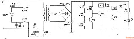
When the level is low, ac voltage of 220V will provide the circuit with 10V dc voltage. VL is illuminated.
When S2 is disconnected, V1 is disconnected. K2-1 and K2-2 are connected, and the motor begins to feed water.
When the level reaches the highest level, S2 is connected, and V1 is connected. K1 K2 are released. M stops working.
When the level is between the lowest and the highest, S2 is disconnected. When the level reaches the lowest, the circuit begins to work again, and M begins to feed water. (View)
View full Circuit Diagram | Comments | Reading(695)
Agricultural Automatic Water Feeder (1)
Published:2011/5/22 19:30:00 Author:Sue | Keyword: Agricultural, Automatic, Water Feeder
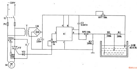
When Q is connected, AC voltage of 220V provides the circuit with 10V DC voltage.
When the level is lower than b, IC’s 2 pin and 6 pin have low level, and 3 pin outputs high level. M begins to feed water.
When the level reaches v, R2 will be short, and IC’s 2 pin and 6 pin have voltage higher than VCC/3,but lower than 2VCC/3. 3 pin outputs high level and M continues to feed water.
When the level reaches a, R1 is short, 3 pin has a low level, and M stops feeding water.
When the level is between a and b, M stops working, until the level is lower than b, M begins to work again.
It works like this and the level can be between a and b. (View)
View full Circuit Diagram | Comments | Reading(585)
Electronic Pest Killing Lamp (2)
Published:2011/5/20 4:00:00 Author:Sue | Keyword: Electronic, Pest, Killing, Lamp
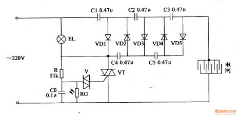
In the daytime, RG's resistance value is low, making CO circuit short. VT is disconnected because of lack of voltage, and the rectifying circuit doesn't work. When there is no light in the evening, RG has a large resistance value. R and CO begin to charge. When CO's voltage reaches a certain value, V and VT are connected. The rectifying circuit begins to work. The alternating current 220V voltage will generate 1450V high voltage, which will be put onto the electric net. When the pest touches the net, it will be killed by the high voltage. (View)
View full Circuit Diagram | Comments | Reading(729)
Water Level Indicator (5)
Published:2011/5/17 20:51:00 Author:Sue | Keyword: Water Level, Indacator
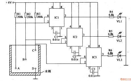
When there is no water, IC1-IC3 will output low level, VL1-VL3 are not illuminated.
When the level is lower than A, IC1’s inside circuit reverses, its 3 pin will output high level, illuminating VL1.
When the level reaches B, IC2’s 3 pin outputs high level, illuminating VL2.
When the level reaches C, IC3’s 3 pin outputs high level, illuminating VL3.
When the level is lower than C, IC3 reverses and 3 pin will have a low level, making VL3 go out.As the level becomes lower, VL2 and VL1 will go out one by one.. (View)
View full Circuit Diagram | Comments | Reading(1457)
Water Level Indicator (4)
Published:2011/5/17 20:46:00 Author:Sue | Keyword: Water Level, Indicator
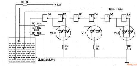
When water level reaches D, D1 will have a high level, and its output terminal has a low level, while D2’s output terminal has a high level. VL1 is green then. When the level is lower than D, D1’s input terminal will have a low level and D2’s output terminal will have a low level, making VL1 become red. Other circuits have the same working principle as this one.
When there is no water or water level is lower than d, VL1-VL3 are red.
When the level is the lowest, VL1 is green, VL2,VL3 are red.
When the level reaches 1/2, VL1,VL2 are green, VL3 is red.
When the level reaches B, VL1-VL3 are green. (View)
View full Circuit Diagram | Comments | Reading(2449)
Agricultural Automatic Water Tap (2)
Published:2011/5/19 3:25:00 Author:Sue | Keyword: Agricultural, Automatic, Water Tap
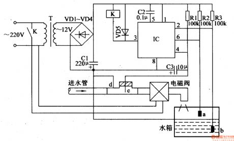
When the water level is lower than v, IC's 3pin will output high level, making K work, and therewill bewater pouring into the water tank. When the level is higher than a, IC's 3 pin will have a low level, and K, magnetic valve will stop working. The water supply will be stopped.
When there is no water in the inlet pipe, IC's 4 pin will have a low level, and IC's 3 pin will output low level. Kand the magnetic valve don't work.
To avoid gas in the water pipe, C3 will be set as time delay capacitor. (View)
View full Circuit Diagram | Comments | Reading(2056)
Agricultural Automatic Water Tap (1)
Published:2011/5/19 3:18:00 Author:Sue | Keyword: Agricultural, Automatic, Water Tap

When the water level doesn’t reach the certain level, the circuit doesn’t work. When there is water in inlet pipe, VL1,VL2’s negative poles will have low level, which will make V1 disconnected and V2 connected. K is connected and YV begins to work, adding water into the water tank.. Then VL2 is illuminated. When the water reaches a certain level, V1 is connected, and V2 is disconnected. K is released, and YV is disconnected. Then water supply is stopped. At the same time, VL1 is illuminated. If there is no water in the inlet pipe, VL2,VL1’s negative poles will have high level, making V1,V2 disconnected, and K, YV don’t work. (View)
View full Circuit Diagram | Comments | Reading(2360)
Agricultural Automatic Water Feeder (15)
Published:2011/5/22 20:41:00 Author:Sue | Keyword: Agricultural, Automatic, Water Feeder
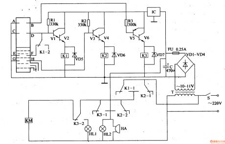
When the level is lower than E,F, V1 and V2 are connected and K1 is connected. KM is connected and M begins to feed water. When the level is higher than C,D, V1 and V2 are disconnected and K is relealsed. KM is released and M stops working. When the level is lower than E,F, M begins to work again.
If C,D or D,F stop working, the protection system will begin to work. When the level is higher than C,D, M is still working. When the level reaches the highest, V5,V6 are connected and KM is released. M stops working. At the same time, the HL1 HL2 will be illuminated. HA will make an alarm sound.Ifthe level is lower than E,F, M is still not working, V3,V4 will be connected and KM is connected. M will begin to feed water. HL2 is illuminated and HA makes an alarm sound. (View)
View full Circuit Diagram | Comments | Reading(654)
| Pages:259/312 At 20241242243244245246247248249250251252253254255256257258259260Under 20 |
Circuit Categories
power supply circuit
Amplifier Circuit
Basic Circuit
LED and Light Circuit
Sensor Circuit
Signal Processing
Electrical Equipment Circuit
Control Circuit
Remote Control Circuit
A/D-D/A Converter Circuit
Audio Circuit
Measuring and Test Circuit
Communication Circuit
Computer-Related Circuit
555 Circuit
Automotive Circuit
Repairing Circuit