
Control Circuit
Index 251
315 remote control circuit
Published:2011/6/9 8:22:00 Author:Lena | Keyword: remote control, circuit
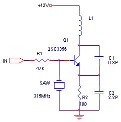
Early transmitters more usually use LC oscillator, but frequency excursion is more graveness. The appearance of sound-surface device solve the problem, the frequency stability is general same as crystal oscillator, but the base frequency can be hundreds of even thousands of MHz. Dispense with multiple frequency, this circuit is more simple than crystal oscillator circuit. These two are common transmitter circuits, because of using sound-surface device, these circuits work very stable. Even if hand antenna, sound-surface or other part, transmit frequency will not excursion.
(View)
View full Circuit Diagram | Comments | Reading(1734)
BA8105(electronic fan) infrared remote control receiving control circuit
Published:2011/6/9 8:50:00 Author:Lena | Keyword: infrared, remote control, receiving
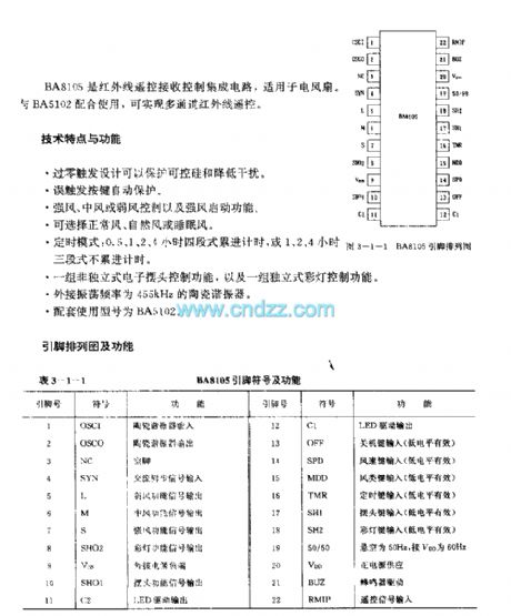
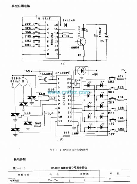

BA8105 is a infrared remote control receive control integrated circuit applied to fans. In Combination of with BA5102, can realize channel infrared remote control.Technology characteristic and functionleakage trigger design can protection controlled silicon and reduce interference.Mis-trigger key self-protectionStrong wind, middle wind or weak wind control and strong wind startup functionThree selections: common wind, natural wind or sleep windTiming mode: 0.5、1、2、4 hour four-flight progression time, or 1、2、4 hour three-flight not progression time.
(View)
View full Circuit Diagram | Comments | Reading(752)
phone remote control monitor circuit
Published:2011/6/9 9:53:00 Author:Lena | Keyword: phone, remote control, monitor

Function characteristic1.remote control household appliances power on/off.2.remote control appliance power on, if delay auto cut-off.3.remote or local change password, simulate off-hooking ring times and all set functions of remote-control unit.4.2-way contact output(connect 220V power supply socket),1-way direct current output(12V),1-way level output(two positive, negative output ends, which can direct connect related appliance control end ).5.second function setting, add remote control monitor function.
(View)
View full Circuit Diagram | Comments | Reading(878)
LM39U(annunciators and self-control devices) singlechip temperature control circuit
Published:2011/6/1 9:38:00 Author:Lena | Keyword: annunciators , self-control devices, singlechip, temperature control
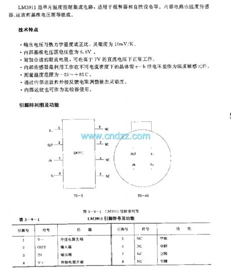

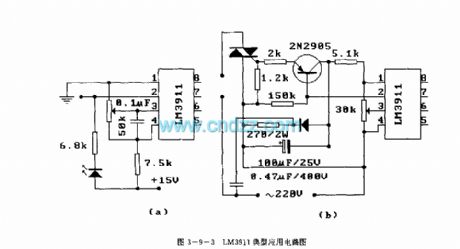
LM3911 is a singlechip temperature control integrated circuit applied to annunciators and self-control devices etc. Internal circuit consists of temperature sensor, operational amplifier and reference voltage source etc.
Technical characteristicOutput voltage is inproportion to the thermodynamics temperature, the sensitivity is 10mV/K.Internal reference voltage source regulation value is 6.8V.Add appropriate current-limiting resistance, which can work at volt d.c above 7V.Internal sensor uses transistor e-b node voltage differences that work at different current density as temperature sensing element.Measurement temperature range is -25~+85℃.
(View)
View full Circuit Diagram | Comments | Reading(702)
△ connection electromotor phase loss voltage relay protection circuit
Published:2011/5/30 1:42:00 Author:Christina | Keyword: △ connection, electromotor, phase loss, voltage relay, protection circuit
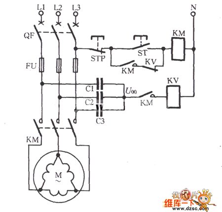
The △ connection electromotor phase loss voltage relay protection circuit is as shown:
For the △ connection electromotor, there need to be a artificial neutral point, we use three equivalent capacitance to form the Y-shape to connect with the electromotor in parallel connection, then we add the protection components at the midpoint of this Y-shape, as the figure shows. When the motor three-phase power is normal operation, the neutral voltage U00 is lower than 10V. If the phase is broken when the electromotor load is operating, the neutral voltage U00 is related with the load, the change range is 10 to 50V. IF we use the DJ131/60CN type voltage relay, the action voltage can be setting in 20 ~ 25V; if the electromotor's load is lower than 50% ~ 60%, the setting voltage is 15 ~ 20V. (View)
View full Circuit Diagram | Comments | Reading(1370)
simple and practical three-key interlock electronic switch circuit
Published:2011/5/29 6:58:00 Author:chopper | Keyword: simple and practical, three-key interlock, electronic switch
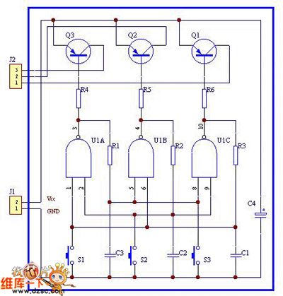
View full Circuit Diagram | Comments | Reading(866)
single-supply,low-voltage,low-consumption operational amplifier circuit
Published:2011/5/29 7:20:00 Author:chopper | Keyword: single-supply, low-voltage, low-consumption, operational amplifier
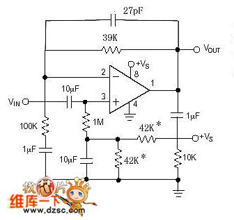
This is a single-supply,low-voltage,low-consumption operational amplifier circuit.The operational amplifier can choose low-voltage series,such as OPA2350,MAX412,OPA2344 and so on.If the supply voltage is 5V,the resistance with * would be 42K;and if the supply voltage is 3.3V,please choose a resistance with 27K.
(View)
View full Circuit Diagram | Comments | Reading(2031)
S1AO903X01 single chip AM/FM digital tuner circuit
Published:2011/5/20 2:29:00 Author:Christina | Keyword: single chip, AM/FM, digital tuner
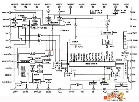
This circuit has three points of features:
(1)The amplitude modulation circuit includes the radio frequency (RF) circuit, the mixer (MIX), the oscillator (OSC), the intermediate frequency (IF) amplifier (AMP), the detector (DET), the automatic gain control (AFC) circuit, the tuning LED driver circuit, the oscillator and the IF buffer circuit.
(2)The tuning circuit includes the RF amplifier, the RF mixer, the oscillator, the IF amplifier, the tuning LED driver circuit, the IF amplifier, the tuning LED driver circuit.etc.
(3)The other circuits are: the PLL, the stereo decoding circuit, the multiple voltage-controlled oscillator (MPX VCO), the LED controller / driver, the AM/FM programmable mixer, the AM/FM IF counter.etc. The internal circuit block diagram is as shown in the figure.
(View)
View full Circuit Diagram | Comments | Reading(2756)
The high sensitivity loud sound alarm circuit
Published:2011/6/10 4:46:00 Author:qqtang | Keyword: high sensitivity, loud sound alarm
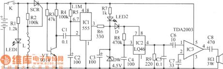
In the figure is the high sensitivity loud sound alarm circuit. This alarm is suitable for orchard security alarm systems. It is very sensitive and loud, so it has a good effect on the thieves, even if there are no guards in the orchard, the owners don't need to worry about their fruit, because the sound of catch the thieves will attract the people's attention and keep thieves away. The alarm is triggered by touch, once it was triggered, even linking the wires again is useless, the sound will be stopped in two minutes. The circuit is easy to make. (View)
View full Circuit Diagram | Comments | Reading(741)
555 sound control floodlight circuit
Published:2011/5/21 23:08:00 Author:TaoXi | Keyword: sound control, floodlight
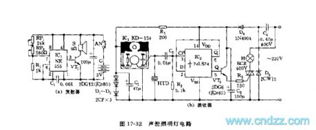
As the figure 17-49 shows, the sound control circuit is composed of two parts: the transmitter and the receiver.
The astable multivibrator is composed of the 555 and RP1,RP2,R1,C1, the oscillation frequency f=1.44/(RP+2R1)C1, the parameters in the figure have the oscillation frequency of about 1~40kHz, the oscillation frequency is adjustable. It drives the high-pitched loudspeaker through VT1. The IC1 of the receiving circuit uses the special whistle integrated circuit KD-154, and the KD-154 is very sensitive to the high voice frequency of 18kHz, when debugging, we adjust RP1 and RP2 to send out the 18kHz audio frequency to drive the KD-154. The HTD is the pickup.
(View)
View full Circuit Diagram | Comments | Reading(515)
555 sound control color light circuit
Published:2011/5/21 22:41:00 Author:TaoXi | Keyword: sound control, color light
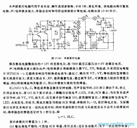
This sound control color light circuit can be used in wide range of applications such as the music room, the dance hall or the karaoke, the home decoration. This circuit is composed of the step-down rectifier circuit, the sound/electricity conversion and amplifying circuit, the monostable timing circuit and the SCR color light control circuit. The circuit is as shown in figure 17-60.
The monostable trigger timing circuit is composed of the IC1(555) and R4,C4. When there is no signal, pin-2 of 555 has the high level voltage because of R2's lifting effect, so 555 is in the reset-state, pin-3 has the low level voltage, LED1 turns off, SCR cuts off; when there is the music or sound signal, this signal is amplified by VT1 and VT2, the negative pulse signal triggers 555, pin-3 outputs the high level voltage, LED1 turns on.
(View)
View full Circuit Diagram | Comments | Reading(624)
555 neon light high-frequency high-voltage source circuit
Published:2011/5/21 22:14:00 Author:TaoXi | Keyword: neon light, high-frequency, high-voltage, source circuit
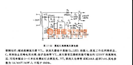
This power supply uses one piece of the time base circuit 555 as the core. The circuit is as shown in figure 17-63.
The multivibrator is composed of the 555 and R1,R2,C2, the oscillation frequency f=1.44/(R1+2R2)C2
The oscillation frequency of the parameters in the figure is 17.8kHz, the output pulse's duty cycle is about 1:1. The output of 555 is cut by D3 and then drives the high frequency amplifier VT1. This amplifier connects with the base electrode D3 and the LED1, so it's working condition is C-class. C5 can be used to prevent the reverse peak voltage, and it protects the transistor VT1. The secondary stage of the amplifier transformer can output the high-frequency voltage of 12500V, and this voltage can turn on the 3 ~ 6 meters neon light.
(View)
View full Circuit Diagram | Comments | Reading(1273)
555 film cans-show lan activity & exposure timer circuit
Published:2011/5/21 8:12:00 Author:TaoXi | Keyword: film, cans-show, lan activity, exposure, timer circuit
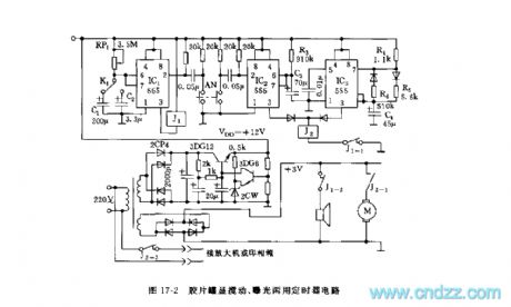
As the figure 17-2 shows, the step-down rectifying power supply spllies the voltage of VDD=+12V to the timer. The timer uses three pieses of 555 as the core. IC1 is the long timing circuit, when you press AN, IC1 and IC2 reset together, IC1's timing time is td1=1.1RP1C1,td2=1.1RP1C2, and the value depends on the different films and different exposure time. When the warning time is up, J1-1's NC contact point cuts off, IC2 and IC3's power supplies are cut off. The 1 minute timer is composed of the IC2 and R3,C3, when you press AN, J2 closes to connect the J2-1.
(View)
View full Circuit Diagram | Comments | Reading(583)
555 simple practical music light control circuit
Published:2011/5/21 7:07:00 Author:TaoXi | Keyword: simple, practical, music lights, control circuit
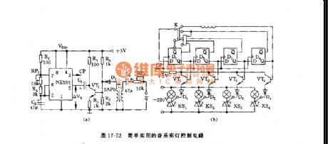
As the figure 17-53 shows, this circuit is composed of the sound control multivibrator, the timing pulse generator and the SCR trigger circuit.etc.
The astable multivibrator is composed of the 555 and R2, RP1, R3, C3.etc. The music signal is detected by the coupling transformers T1 and D1, and it is amplified by VT1, then it adds to the 555's control port pin-5. Pin-5 connect with the standard partial pressure point (2/3VDD) of the integrated chip's internal comparator.
This circuit can produces five kinds of cycle way to make the flash to change with the music, so it can be used in the dance floors or the celebration occasions.
(View)
View full Circuit Diagram | Comments | Reading(704)
555 simple printing & amplification timer circuit
Published:2011/5/21 6:43:00 Author:TaoXi | Keyword: simple, printing, amplification, timer circuit
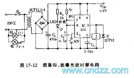
As the figure 17-12 shows, the timer is composed of the step-down rectifier circuit and the monostable circuit.
The monostable timing circuit is composed of the 555 and the C2, the photoresistor RG, when using, you need to press AN, the 555 sets, J1-1 connects, the white light turns on. The light shine on the RG through the film, according to the film's transmittance, RG presents the different resistances, so the monostable delays are different too. The delay time td=1.1RGC2. When the temporary stability time is up, J releases, the white light turns off, the red light turns on, so the automatic exposure is finished.
(View)
View full Circuit Diagram | Comments | Reading(572)
The auto door control circuit
Published:2011/6/10 2:20:00 Author:qqtang | Keyword: auto door, control circuit
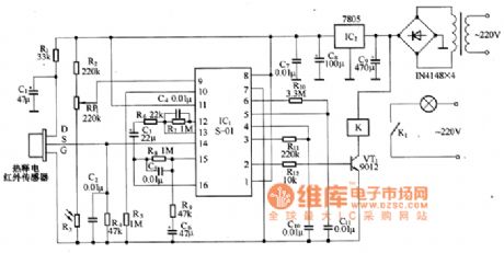
In the figure is the auto door control circuit. The human body movement detection is done with the new heat infrared probe module HN911. VT1 is the time delay control, by adjusting potentiometer RP1, the delaying time can be changed. The photocoupler MOC3020 is functioning as the D/A current separator. When there is no one walking, HN911 output terminal 1-pin is in a low LEV, VT1 controls the signal output, the dual-way thyristor Vh is closed, the loading motor is not working, and the gate is in the closed state. When someone is getting close to the auto gate, HN911 is detecting the infrared energy of human body.
(View)
View full Circuit Diagram | Comments | Reading(2118)
The timer circuit with display function
Published:2011/6/10 1:55:00 Author:qqtang | Keyword: timer circuit, display function
The features of the timer are: (1) wide timing period. The starting up time and keeping time range from several seconds to 2h, both of which are continuous and adjustable; (2) starting up and keeping time are marked with two colors, and either of them is indicated with 10 LED, so the rest time in clear; (3) the timer can work once, or work repeatedly; (4) when the timer is not working, it can be used as an outlet; (5) the timer is equipped with general gate circuits, triggers, counters and so on, which is suitable for teaching practices of universities and colleges. (View)
View full Circuit Diagram | Comments | Reading(1516)
The loudspeaker protection circuit
Published:2011/6/10 2:33:00 Author:qqtang | Keyword: protection circuit
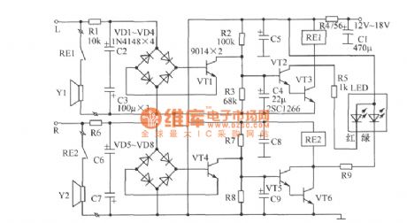
In the figure is the loudspeaker protection circuit. The circuit is designed to have the left and right channels and they work separately.Elements selection: the LED can be the Φ3mm high brightness dual color LED. As the working current can be large or small. The parameters of R5 and R9 and be slightly adjusted. At the same time, LED and current limiting resistors R5 and R9 are connected with the two terminals of the relays (RE1 and RE2), so the inverting peak voltage can be impeded and VT2, VT3, VT5 and VT6 won't be broken down. It is better to choose low-leakage Tantalum capacitors for C4 and C9. The parameters of other elements are shown in Figure 1. (View)
View full Circuit Diagram | Comments | Reading(1579)
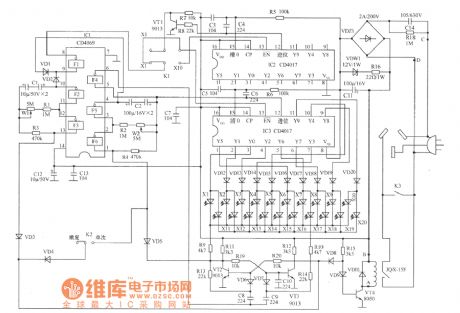
The electric bonsai circuit
Published:2011/6/10 2:48:00 Author:qqtang | Keyword: electric bonsai
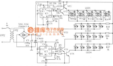
Element selection: IC1~IC4 are two slices of dual D triggers CD4013; all the transistors VT are installed with 9013 PNP silicon triodes and so on, β>90. The types of LED are not limited, to achieve the flash effect, even the 5 LED in the same time may be of different colors. If the number of the LED is too small, it can be added, but the a little bigger transistors should be used, such as 8050 and DD01,etc. R10~R14 are the resistors of 470Ω. C1~C8 are the electrolytic capacitors of 1001μF/16V. S is a micro light touch power supply switch of CS-316. T is a micro power supply transformer of 220V/10V and 5W. (View)
View full Circuit Diagram | Comments | Reading(846)
The LED AC drive circuit
Published:2011/6/10 2:57:00 Author:qqtang | Keyword: AC drive circuit
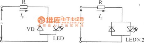
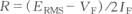
See as the figure, the circuit can work normally under the condition whether the polarities of the voltage or power supply are right or not is unknown. As DC drive, when it is AC driven, the value of the limited resistance R is .In the formula, ERMS is the effective value of the AC current. (View)
View full Circuit Diagram | Comments | Reading(1000)
| Pages:251/312 At 20241242243244245246247248249250251252253254255256257258259260Under 20 |
Circuit Categories
power supply circuit
Amplifier Circuit
Basic Circuit
LED and Light Circuit
Sensor Circuit
Signal Processing
Electrical Equipment Circuit
Control Circuit
Remote Control Circuit
A/D-D/A Converter Circuit
Audio Circuit
Measuring and Test Circuit
Communication Circuit
Computer-Related Circuit
555 Circuit
Automotive Circuit
Repairing Circuit