
Control Circuit
Index 247
The over-voltage protection circuit (1)
Published:2011/6/14 2:42:00 Author:Christina | Keyword: Over-voltage, protection
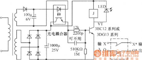
The over-voltage protection circuit is as shown in the figure. This circuit uses the photoelectric coupler's on-off to control the device. When the voltage is normal, the photoelectric coupler has no output, the VT tube cuts off because of the reverse bias. When some reasons increase the voltage of this circuit, the voltage of the sampling circuit subprime stage will increase too, the photoelectric coupler meets the working condition. The light-coupler output current increases the VT tube's bias voltage and make the VT tube to conduct, the actuator's relay closes and cuts off the power supply to protect the electrical equipment. If the fault is eliminated, the voltage will be normal, this circuit will immediately quit the working condition to recover the power supply of the circuit. (View)
View full Circuit Diagram | Comments | Reading(697)
using DH-03C pyroelectric infrared to control delay spotlight circuit
Published:2011/5/19 7:22:00 Author:Lena | Keyword: pyroelectric infrared , delay, spotlight

(View)
View full Circuit Diagram | Comments | Reading(439)
The temperature control circuit
Published:2011/6/13 22:23:00 Author:Christina | Keyword: Temperature, control
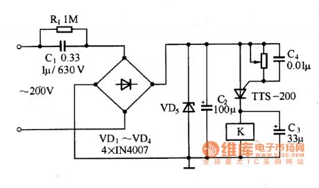
The temperature control circuit is as shown in the figure. This circuit is composed of the capacitance step-down circuit, the bridge rectifier circuit and the diode voltage regulator circuit. The diode voltage regulator circuit supplies the operating voltage for the temperature control thyristor, the control circuit is composed of the relay. The value of capacitor C1 can be selected by the size of the relay operating current, the zener VD5 should be determined according to the relay's operating voltage.
Figure: The temperature control circuit (View)
View full Circuit Diagram | Comments | Reading(851)
Light load Energy Saver of Motor(the 1st)
Published:2011/5/19 8:04:00 Author:Felicity | Keyword: Light load Energy Saver of Motor,
Work of the circuit
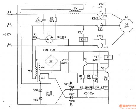
Once it is powered, 380V AV voltage will be supplied to motor M through reator LTl-LT3. In the same time current transformer TA will produce sensor signal voltage which will make V1 and V2 saturated conducted. Then the motor will work with full voltage. When the motor is work it maybe has light load or even no load. So the sensor signal voltage on current transformer TA will reduce and this leads to the motor's decompressed operation. When the motor's load is becoming heavier, and the sensor signal voltage on current transformer TA reaches a vertain figure, the motor will work with full voltage. (View)
View full Circuit Diagram | Comments | Reading(702)
Use the timer to judgment the quality performance of photoelectric couplers
Published:2011/5/22 7:27:00 Author:Crystal Liu | Keyword: quality performance of photoelectric couplers, timer
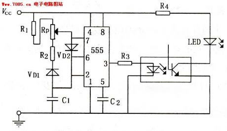
NE555 adopted the circuit shows in figure 1 below,VD1 and VD2 role is sepatating capacitance C1 charge-discharge loop,in order to make the timer output 390v adjustable pulse waveform;C2isfilter capacitance,capacity is 0.01uF,Its role is comprised of timing devices;Resistance of R1,R2 respectively is 10kΩ and 51kΩ;The resistance of Rp is 0—10kΩ;The resistance of R3 and R4 respectively is 2kΩ and 1kΩ.Their action all is for the current limit;Vcc can use dry cell or dc voltage stabilizer.
(View)
View full Circuit Diagram | Comments | Reading(527)
M50460—012P(TV) infrared remote control transmitting control circuit
Published:2011/6/1 9:34:00 Author:Lena | Keyword: infrared, remote control, transmitting, control circuit
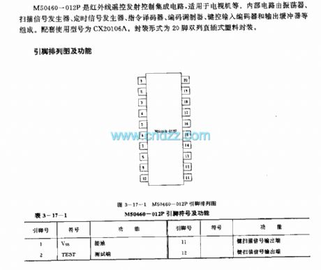
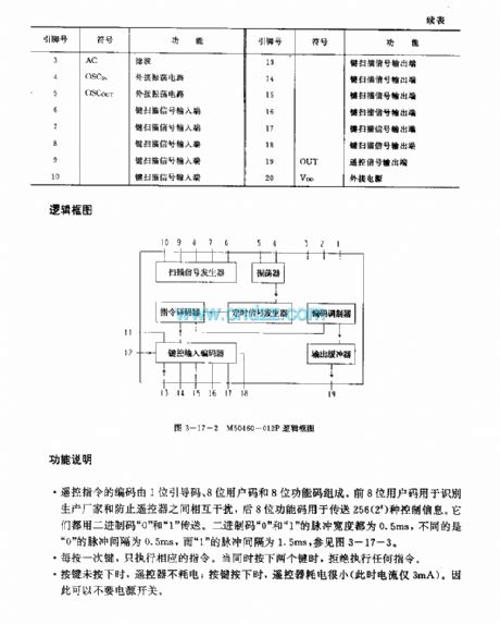
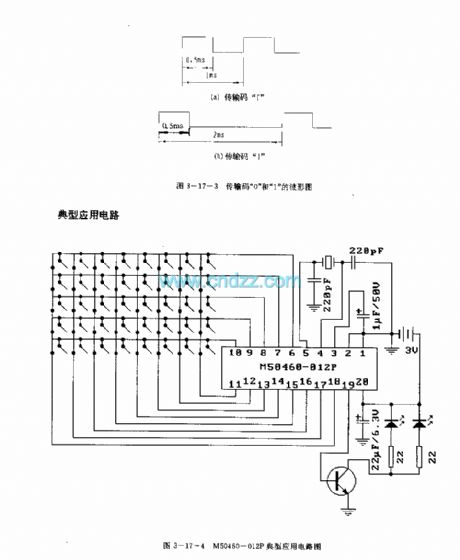
M50460-012P is an infrared remote control transmitting control integrated circuit which is applied to TV etc. Internal circuit consists of oscillator, scan signal generator, timing signal generator, instruction encoder, coding modulator, key control input coder and output buffer. Related used type is CX20106A. Package model is 20-pin dual-in-line plastic package.
Function descriptionRemote control instruction is composed by 1-bit leader code, 8-bit user code and 8-bit function code. The anterior 8-bit user code is used to identify producer and to prevent interference between remote controllers.
(View)
View full Circuit Diagram | Comments | Reading(887)
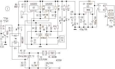
Infrared Ray Detection Alarm
Published:2011/5/16 4:46:00 Author:Sue | Keyword: Infrared Ray, Detection, Alarm
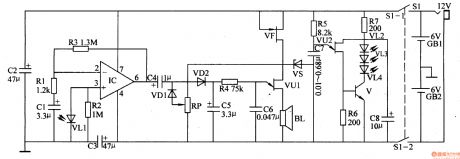
When S1 is connected, infrared ray emission circuit begins to workwith a certain frequency, and outputs infrared ray pulse through VL2-VL4. When VL has no objects in from of it, IC's 6 pin outputs no signal.
When VL has objects in front of it within 1.5m, infrared ray signals emitted by VL2-VL4 will be absorbed by VL1 after reflection. VL1 will turn the ray signal into electric signal, and send it into IC to amplify signal. The electric signal after being amplified by IC will make the audio oscillator begin to work and promote the loudspeaker BL to make a warning sound. (View)
View full Circuit Diagram | Comments | Reading(617)
Frost Alarm (1)
Published:2011/5/16 3:13:00 Author:Sue | Keyword: Frost, Alarm
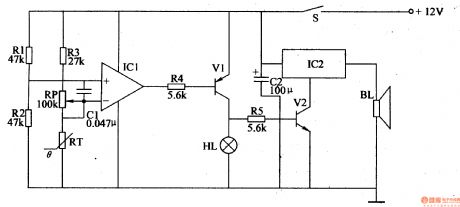
Working Principle:
When there is no frost, the temperature is relatively high, so RT's resistance value is low. IC's syntropy input terminal will have a higher voltage than its reverse input terminal. The output terminal will output high level, making V1 and V2 disconnected, HL is not illuminated. IC2 doesn't work and BL makes no sound.
When there is frost, the temperature becomes lower,so RT's resistance value will be higher, making IC's reverse input terminal have a higher voltage than its syntropy input terminal. The output will have low level, making V1 and V2 connected, and HL is illuminated. IC2 begins to work and BL makes a warning sound. (View)
View full Circuit Diagram | Comments | Reading(701)
M494 (TV)infrared remote control receiving microprocessor
Published:2011/6/1 9:38:00 Author:Lena | Keyword: infrared, remote control, receiving, microprocessor
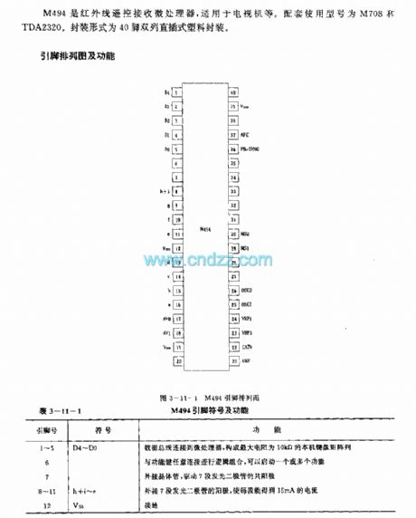
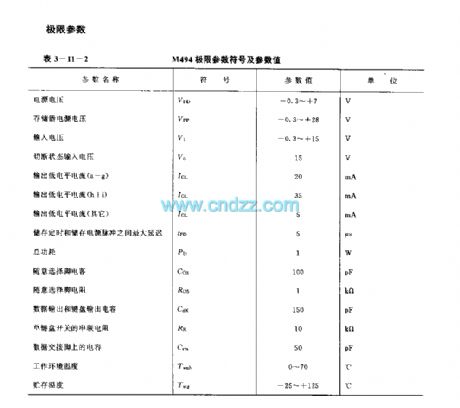
M494 is an infrared remote control receiving microprocessorappliedto TV etc.The related types are M708 and TDA2320.Package form is a 40-pin dual-in-line plastic package.
Functions:
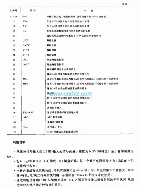
*Minimum radius of input signal from remote signal input end(35th pin) is 0.5V(peak-to-pwak value),minimum pulse width is 8μs.
*Row(a-g) and line(D0-D4) form a 5×4 keyboard matrix,every key usesresistant(maximum value is 10KΩ)connecting rows and lines.
*The circuitcan prevent bounce.That is when a key closing more than 40ms,relevant instruction can be received;the key related to
boot-strap/standby,boot-strap/shutdown instructions,must close more than 100ms, the instruction can be received.
*Different states obtainedthrough function select end (6th pin) and keyboard line(D0-D4) whether or notconnecting a diode,to select function.
(View)
View full Circuit Diagram | Comments | Reading(556)
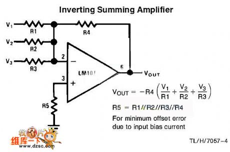
Inverting Summing Amplifier Circuit
Published:2011/5/31 7:47:00 Author:chopper | Keyword: Inverting Summing Amplifier
View full Circuit Diagram | Comments | Reading(2103)
level-8 touch volume controller of 74L194 circuit
Published:2011/5/11 4:56:00 Author:chopper | Keyword: touch volume controller, level-8
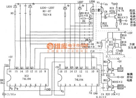
As shown in figure is a level-8 touch volume controller of 74L194 circuit.Multivibrator type oscillator,shifting register,touch control circuit,impedance inverter circuit form the circuit.The oscillatory frequency of multivibrator type oscillator composed of IC1(555) and R18,R19,C2 is f=1.44/(R18+2R19)C2,and the corresponding frequency of parameter in the figure is about 2Hz.The outputing square signal acts as shifting clock pulse of IC2,IC3.IC2,IC3 are bidirectional shift-registers 74LSl94,and they two concatenate to be a shift-register.IC2,IC3 will be cleared when it meets a boot-strap,and Q0~Q7 are all low level.The circuit is unchangeable and the volume is the least.The S0(pin ⑨)of IC2,IC3 is high level when we touch the sheet metal A by hands,and IC2,IC3 reach a serial rightward shift,makingLED0~LED7 illumine one by one.At the same time,with the electric current,LED8 reaches a staged growth and becomes more brilliant.The resistance of corresponding photoresistor Cds decreases,and the volume inceases gradually.The range of fluctuation is controlled by the time of touching A.When we touch metal B,IC1,IC2 will reach a serial leftward shift because the the S1(pin ⑩) is high level,makeing the volume diminish gradually. (View)
View full Circuit Diagram | Comments | Reading(1394)
Time Delay Shutdown Circuit
Published:2011/5/27 7:59:00 Author:Robert | Keyword: Time Delay, Shutdown

The leftmost is RC time delay circuit and discharging diode. The middle is the circuit set for shutdown and you can regard it as a power supply. The rightmost circuit is used for simulate audio signals.
(View)
View full Circuit Diagram | Comments | Reading(1248)
Automatically Illuminating Doorbell Circuit
Published:2011/5/17 5:53:00 Author:Robert | Keyword: Automatically Illuminating, Doorbell
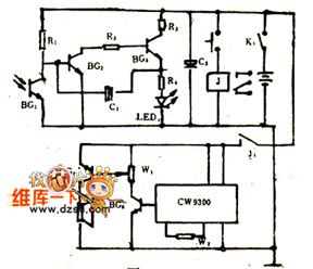
It's difficult to find the doorbell button when at night and the veranda has no light, especially for the visitors who come firstly and they could only knock the door. If the doorbell button switch has been installed a LED which could automatically illuminating at night and automatically closed during the day, it would be convenient for visitors. When the power switch K1 is connected, the phototransistor triode BG1's resistance would be low because of the light during the day, and BG2 base voltage would be low to make BG2, BG3 close. So the circuit would stop working and the LED would not illuminate.
(View)
View full Circuit Diagram | Comments | Reading(554)
Stepper Motor Typical Application Circuit
Published:2011/5/19 6:15:00 Author:Robert | Keyword: Stepper Motor, Typical Application
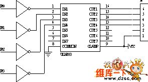
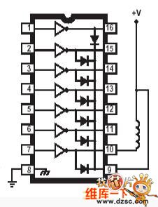
The ULN2003A type high-voltage large-current darlington transistors array circuit's typical application circuit diagram is shown in the picture below. The clamping diode is used for protecting the integrated circuit from been punctured by the EMF when the coil is connected or disconnected. It can be seen that this circuit's application is very simple.
The stepper motor typical application circuit is shown below.
(View)
View full Circuit Diagram | Comments | Reading(1004)
Widely used IC monolithic multiplication circuit
Published:2011/5/11 5:49:00 Author:Fiona | Keyword: IC monolithic multiplication
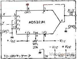

Circuit functionIn addition to be general multiplication, Analog multiplication has many other uses, such as balanced modem, synchronous detection, voltage controlled attenuator, oscillators. This circuit is a basic wiring diagram of an analog device company’s single IC multiplier AD532. Because it has been minute adjusted by the laser in-house, it can remove potentiometer that being used to adjust the X, Y input set of partial balance, just adjusts the output as long as the home side.
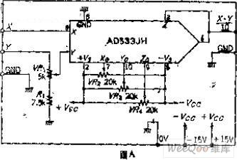
Circuit WorkAD532 is a differential input of the four-quadrant multiplier. It can be EO = [(X1-X2) * (Y1-Y2)] / 10 op. The input voltage range is 0 ~ +10 V, usually uses 1 / 10 scale factor.IC internal is multiplication unit composed of multiplier circuits known as Gilbert , the output impedance is low and no needs external components. The internal IC has been minute adjusted by the laser, there is no need cumbersome adjustment.The circuit only has the output offset adjustment V.AdjustmentBecause the circuit only has the offset adjustment, it only illustrates the AD533 that has not be minute adjusted.In Figure A just has one more variable resistor.It can use the basically same adjustment with the AD532.
(View)
View full Circuit Diagram | Comments | Reading(1017)
achieving multiply the analog input and digital data R.SINθ conversion circuit
Published:2011/5/12 5:06:00 Author:Fiona | Keyword: achieving multiply the analog input and digital data, R.SINθ conversion
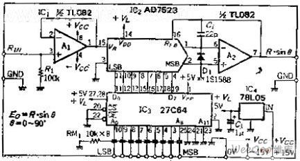
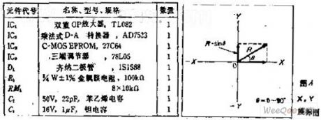
Circuit function
he circuit outputs Y (Y = R. SINθ) function (in Figure A,X, Y is as coordinates, R is representative of the analog input, Y is representative of the function output),θ's selected range is 0 to 90 degrees.90 to 180 degrees and 0 to 90 happens is reciprocal.To make the data can wait until 180 degrees, the control signal uses two BCD code +1 data bits.
Circuit Work
This is an analog input and digital data multiplication circuit which does the R computing and the digital data values is from 0 to 255.In advance, make the ROM data corresponding to the sine function good,because AD7523 is a positive logic input,SIN0 degree = 0, D = 00; SIN90 degree = 1, D = FFH (255/255 ≈ 1).Calculate SIN0 ~ 90 degrees to a degree level,then multiply by 25and switch to binary data to store in the P-ROM.
(View)
View full Circuit Diagram | Comments | Reading(763)
Adjustable timing hige automatic switch circuit
Published:2011/6/8 6:46:00 Author:Fiona | Keyword: Adjustable timing hige automatic switch
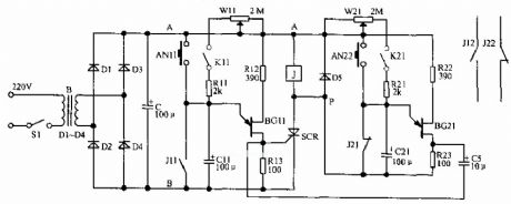
Button switch AN11, AN2 is manual on and off. K11 and K22 is a separate automatic delay on and off. When connecting the power, the circuit charges to the C11 through the W11 and R11, when the voltage of the capacitor is above the peak of BG11, BG11 conducts to trigger the SCR conducts, the relay J is energized pick, J12 and J22 moves to control appliances. J11 closes to discharge the charge on the C11, BG11 closes. During the regular open, when SCR guides energy,point P is equivalent to grounding, often close point J12 is off, by the current charges to C21 through W21 and R21, when the voltage of C21 ends is higher than the peak of the BG21, BG21 conducts, the output signal makes SCR off by C5, the relay disconnects after losing the power, circuit resets.
(View)
View full Circuit Diagram | Comments | Reading(656)
Composed of one-way silicon controlled simple touch switch circuit
Published:2011/6/7 20:01:00 Author:Fiona | Keyword: Composed of one-way silicon controlled
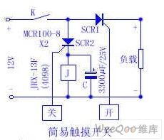
Touch the metal piece to open, SCR1 turns on, the load is energized to work. Touch the metal piece off, SCR2 turns on, the relay J is energized to work,K is off, the load losses the power, SCR2 turns off, the capacitance discharges to the relay J, it keeps the relay pulling in about 4 seconds, so the circuit action is more accurate. If the load replays to the relay, it can control the large current work load. Friends who are interested, give it a try. (View)
View full Circuit Diagram | Comments | Reading(1036)
SCR over-current protection circuit with the Hall components
Published:2011/5/17 22:03:00 Author:TaoXi | Keyword: SCR, over-current protection, Hall components
Related components PDF download:
ULN302067L070
Here we introduce one kind of SCR over-current protection circuit that uses the Hall components as the sensor, it has the overheat protection function and the sound and light alarm function. The principle circuit is as shown in figure 1.
The IC1 and IC2 are the Hall integrated circuit ULN3020, in the normal operation, their output port pins always have the low level voltage, D2 and D3 close, the SCR T1 is in the shutdown state, LED L4 does not light, the positive power supply form a loop through the R6, L1, IC4, R5, VT and the ground, if the base port of the control switch transistor VT has the high level voltage, it is in the conduction-status to open the zero-crossing trigger IC4 and also to trigger the two-way silicon T3, the load RL gets the power to work, their current will generate an alternating magnetic field in the magnetic circuit, if the peak value of the magnetic field intensity does not reach the two hall components' opening magnetic field strength, IC1 and IC2 will be maintained the original state. (View)
View full Circuit Diagram | Comments | Reading(950)
555 high-performance streetlights photoelectric control circuit
Published:2011/6/2 18:47:00 Author:TaoXi | Keyword: high-performance, streetlights, photoelectric control

As the figure 17-30 shows, the photoelectric conversion element RG uses the photoresistor, when there is the light, it has the low resistance; when there is no light, it has the high resistance or in the open state. IC1 is the comparator circuit, when RG is lighted and has the low resistance, 555 sets, Jwillnotact, LED1 turns off. At night, RG has the high resistance, pin-2 has the high electric potential, because pin-6 connects with VDD, so 555 resets, J closes and LED1 turns on.
The action locking loop is composed of the IC2 and VT1,VT2. IC2 is the monostable timing circuit, the timing time td=1.1R7C6, it is about 10 minutes.
(View)
View full Circuit Diagram | Comments | Reading(509)
| Pages:247/312 At 20241242243244245246247248249250251252253254255256257258259260Under 20 |
Circuit Categories
power supply circuit
Amplifier Circuit
Basic Circuit
LED and Light Circuit
Sensor Circuit
Signal Processing
Electrical Equipment Circuit
Control Circuit
Remote Control Circuit
A/D-D/A Converter Circuit
Audio Circuit
Measuring and Test Circuit
Communication Circuit
Computer-Related Circuit
555 Circuit
Automotive Circuit
Repairing Circuit