
Control Circuit
Index 254
Touch socket circuit
Published:2011/6/8 6:57:00 Author:Christina | Keyword: Touch, socket
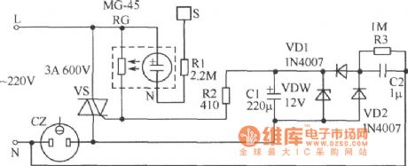
The circuit is as shown in the figure, when your finger touches the sheetmetal S, the neon tube N lights, the photoelectric coupler which is composed of the N and the photoconductive resistance RG to decrease the resistance of RG, the two-way thyristor VS gets enough trigger current to conduct, so the load of the socket CZ gets power to work. At the same time, the 220V AC voltage of CZ is reduced by the capacitance C2, then is rectified by the diodes VD1 and VD2, and this AC voltage is also regulated by the regulator tube VDW and filtered by the capacitance C1, at last it changes into the DC voltage and adds to the VS's control port through the resistance R2, so even the finger has left, VS is still in the conduction state to keep the load working normal. (View)
View full Circuit Diagram | Comments | Reading(620)
MC45162 programmable phase-locked loop frequency synthesis modulation and demodulation integrated circuit
Published:2011/6/8 22:32:00 Author:Christina | Keyword: programmable, phase-locked loop, frequency synthesis, modulation, demodulation, integrated circuit
The MC45162 is designed as one kind of programmable phase-locked loop frequency synthesis modulation and demodulation integrated circuit that is produced by the MOTOROLA company, it can be used in the communication equipments.
1.Pin functions
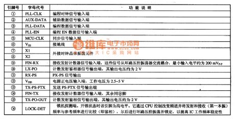
The MC45162 is in the 16-pin double-row DIP package, the letter code and the pin functions are as shown in the table.
2.Typical application circuit
The typical application circuit of the modulation circuit which is composed of the MC45162 is as shown in the figure.
The letter code and the pin functions of the MC45162
(View)
View full Circuit Diagram | Comments | Reading(706)
Light control relay circuit
Published:2011/6/8 7:03:00 Author:Christina | Keyword: Light control, relay
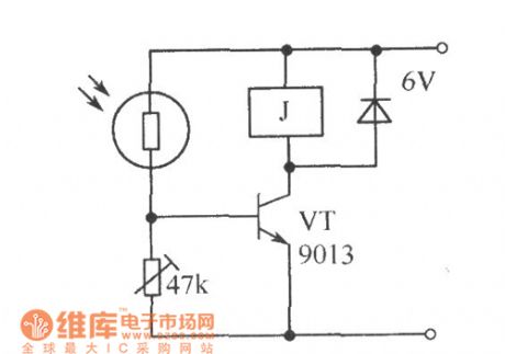
Use the photoconductive resistance as the photoelectric switch circuit, the sensitivity of it is very high, the light control relay circuit is as shown. When the illumination intensity is low, the VT will not conduct; when there is a certain illumination intensity, the resistance of the photoconductive resistance will be small, VT gets enough base current to conduct, so it produces the large collector current to close the relay. (View)
View full Circuit Diagram | Comments | Reading(681)
MH8822 fan single chip computer control integrated circuit
Published:2011/6/8 22:20:00 Author:Christina | Keyword: fan, single chip, computer control, integrated circuit
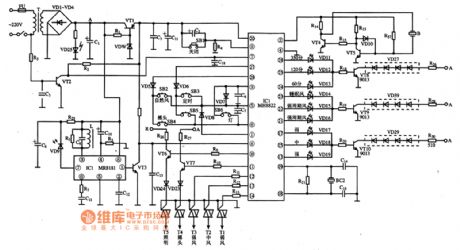
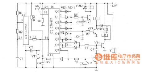
The MH8822 is designed as one kind of fan single chip computer control integrated circuit, it can be used in the control systems of all kind of fans such as the Great Wall series remote control fan.etc.
1.Features
The MH8822 integrated circuit is composed of the clock oscillating circuit, the reset circuit, the button switch instruction decoding circuit, the fan motor speed control circuit, the working condition and timing time indicator light display driver circuit, the buzzer driving circuit, the sync signal processing circuit and the remote control signal processing circuit.etc.
2.Pin functions and data
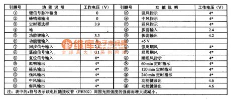
The MH8822 integrated circuit is in the 28-pin double-row DIP package, the pin functions and data is as shown in the table.
The pin-5 functions and data of the MH8822 integrated circuit
3.Typical application circuit
The typical application circuit of the fan control system which is composed of the MH8822 integrated circuit is as shown in the figure.
(View)
View full Circuit Diagram | Comments | Reading(1554)
Novel door light switch circuit
Published:2011/6/8 7:20:00 Author:Christina | Keyword: Novel, door light, switch
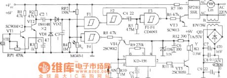
The door light switch that is installed outside the door is always opened and closed by other people, so it is very easy to be damaged, therefore we make the novel door light switch. This door light switch is the knock type, and it has the function of doorbell. The circuit is as shown in the figure, it is composed of the knock detection circuit, the door light trigger and delay control circuit, the doorbell circuit and the power supply circuit.etc. The F1~F4 use the CD4093 digital integrated circuit. The music integrated circuit uses the KD-156. The VT1 and VT2 use the audion SC9014; the VT3 uses the audion SC9013; the VT4 uses the 2SC9012; the VT5 uses the 2SC8050. (View)
View full Circuit Diagram | Comments | Reading(637)
Delay energy-saving light circuit
Published:2011/6/8 8:07:00 Author:Christina | Keyword: Delay, energy-saving, light
The delay energy-saving light circuit is as shown, this device is designed as one kind of sound and light double control delay energy-saving light. The bridge rectifier circuit is composed of the diodes VD1~VD4 and this circuit changes the city electricity into the pulse DC current, this DC current is limited by R7, regulated by VD5 and is filtered by C3, at last it becomes the 8V direct current to supply power for the integrated block CD4011 and the audion VT7. Components selection: the NAND gates D1~D4 can use the 2 input ports four NAND gates CD4011 digital integrated circuit. VS is the MCR100-8 type small plastic one-way thyristor. The rectifier diodes VD1--VD4 can use the 1N4007 type ordinary silicon rectifier diodes, the VD5 uses the 2CW56 type 8V zener diode, the VD6 can use the 1N4148 type ordinary silicon switch diode, the VT7 can use the 9013 type NPN transistor. (View)
View full Circuit Diagram | Comments | Reading(994)
blackout floodlight circuit
Published:2011/6/8 8:18:00 Author:Christina | Keyword: blackout , floodlight
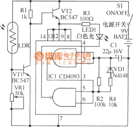
When the children are studying at night, once the blackout, the children can see nothing in the study room, it is not safe. The blackout floodlight circuit which is composed of the light-emitting diode can solve this problem. This light uses the batteries as the power supply, the power consumption is very small, you can put it on the top of the desk, if it is blackout, the light-emitting diodes will turn on automaticly to supply strong enough light, so the children can walk out of the room. In order to reduce the power consumption, the LEDs use the flash illumination mode. The IC1 uses the CMOS integrated circuit CD4093. The VT1 and VT2 use the audion BC547. The LED1 uses the Φ8mm white light-emitting diode, the other components are as shown in the figure. (View)
View full Circuit Diagram | Comments | Reading(886)
Long delay light control switch circuit
Published:2011/6/8 8:33:00 Author:Christina | Keyword: Long delay, light control, switch
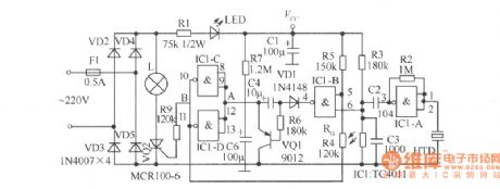
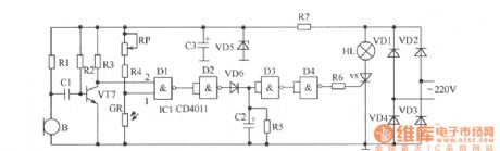
The second generation sound and light control switch is as shown in the figure, the delay time is extended to about 3 minutes, so that it can satisfly meet the requirements of users, and if you want to extend the delay time when you are using it, you just need to send out any sound when the bulb is flashing. Components selection: the IC1 uses the double-input Four NAND gates TC4011. The RG is the photoresistor, the larger the difference between the light resistance value and the dark resistance value, the effect is better. The resistance uses the 1/8W carbon membrane resistance. The electrolytic capacitor voltage is 16V, C6 uses the electrolytic capacitor with good performance and large leakage resistance value. (View)
View full Circuit Diagram | Comments | Reading(594)
Sound control delay desk lamp circuit
Published:2011/6/8 8:43:00 Author:Christina | Keyword: Sound control, delay, desk lamp
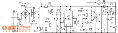
The telephone desk lamp is as shown in the figure, when the telephone rings or off-hook at night, the light will turns on automaticly, after you hang up the telephone, the light will turn off in 45 seconds. In peacetime this telephone desk lamp can be used as the general dimming desk lamp, and it does not need the light switch. When this telephone desk lamp is used as the delay lamp, you just need to touch the delay button, this lamp will turns off in after 45 seconds. This circuit has multi-purpose, and it is composed of the optocoupler circuit, the light control circuit, the negative pulse generating circuit, the monostable trigger circuit, the thyristor switching circuit and the power supply circuit. (View)
View full Circuit Diagram | Comments | Reading(662)
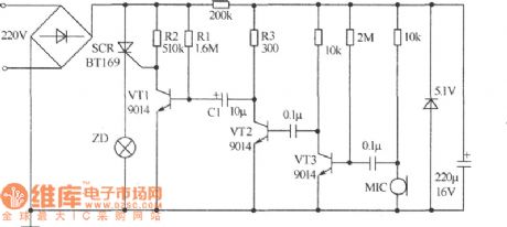
Circuit principle gas furnace flameout alarm circuit
Published:2011/6/8 8:56:00 Author:Christina | Keyword: Circuit, principle, gas furnace, flameout, alarm
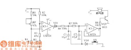
Although some advanced gas furnaces have the automatic flameout protection device, but the price is too high so they are difficult to popularize. The gas furnace flameout alarm circuit is as shown in the figure, this circuit can monitor the gas furnace and alarm. The circuit's core device is the LM324 quad op amp. The IC1-1 is used as the comparator, the IC1-2 is used as the follower; the R4 and R5 are the photoresistor, the resistance changes with the light intensity; AN is the reset switch, AN can be used to discharge the electric charges of capacitance C1 and C2; when you are using it, you need to aim the photoconductive resistance R4 at the flame, then turn the adjusting knob to make the alarm will not alarm. If you use your hand to keep out the flame, the alarm will alarm. This circuit uses the 9V lapped battery. (View)
View full Circuit Diagram | Comments | Reading(765)
Wireless alarm circuit with multiple detection heads
Published:2011/6/8 18:55:00 Author:Christina | Keyword: Wireless, alarm, multiple, detection heads
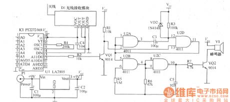
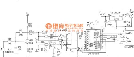
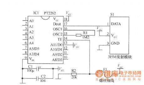
This alarm device separates the detection part and the alarm part, one alarm has multiple detection heads, the detection part and the alarm part use the radio waves to communicate. It has the wireless alarm receiving part and the wireless alarm test launch part. The wireless alarm receiving part is composed of the 315MHz wireless data receiving module, the decoder integrated circuit PT2272-M4, the monostable circuit and the audio generator. The circuit is as shown in the figure.
The wireless alarm test launch part has some detection circuits.
(1)The launch circuit which is composed of the photoconductive resistances:
(3) magnetic induction transmitter circuit:
(View)
View full Circuit Diagram | Comments | Reading(2804)
MIP0254SP micro-consumption single chip switch power supply integrated circuit
Published:2011/6/8 22:08:00 Author:Christina | Keyword: micro-consumption, single chip, switch, power supply, integrated circuit
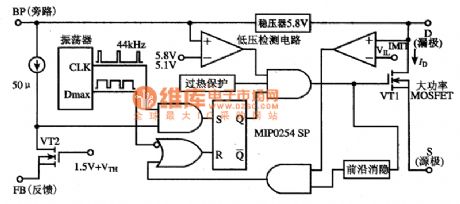
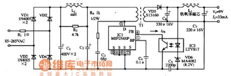
The MPO254SP is designed as a wide voltage range micro-consumption single chip switch power supply integrated circuit, and it can be used to make all kinds of AC adapters.
1.Features
The MPO254SP is composed of the high power MOSFET (the VDS is 700V), the oscillator, the high voltage power supply and the current limiter.
2.Internal circuit block diagram and the pin functions
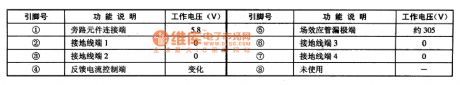
The MIP0254SP integrated circuit is in the 8-pin DIP package, the internal circuit block diagram is as shown in the figure, the pin functions and data is as shown in the table.
The internal circuit block diagram of the MPO254SP
The pin functions and data of the MPO254SP
3. The typical application circuit
The typical application circuit of the MP02545P is as shown in the figure.
(View)
View full Circuit Diagram | Comments | Reading(1359)
Audio monitoring system circuit
Published:2011/6/8 20:23:00 Author:Christina | Keyword: Audio, monitoring system
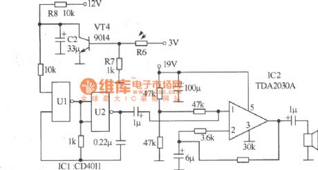
This audio monitoring system circuit uses the fuzzy judgment method, it continuously monitor the audio for 3 seconds every 6 seconds, the interval time and the detection time are adjustable. The working process is: If it detects the sound, the audio indicator light will turn on for 6 seconds. If it does not detect the sound signal, it will continuously monitor for 3 seconds, if there is the sound signal, the indicator light will turn on for 6 seconds, if there is no sound signal in the 3 seconds, the indicator light will turn off and it will send out the alarm for 0.5 second, after the alarm, the circuit will keep the non-detection state for 6 seconds, then repeats the above examination process. The circuit is as shown in the figure.
(View)
View full Circuit Diagram | Comments | Reading(637)
Oil furnace control circuit composed of the common integrated block
Published:2011/6/8 20:42:00 Author:Christina | Keyword: Oil furnace, control circuit, common, integrated block
This circuit can be used as the controller of the small oil furnace. Previous small oil furnace controller uses the integrated block of application-specific integrated block or the microcontroller, they are difficult to buy in the small and medium size cities, so the maintenance is difficult. This small oil furnace controller has the features of reliable performance, simple structure, low cost and convenient maintenance, we can use it in any kinds of oil furnaces by changing the connection mode. (View)
View full Circuit Diagram | Comments | Reading(700)
ML8204 electronic bell integrated circuit
Published:2011/6/8 21:55:00 Author:Christina | Keyword: electronic bell, integrated circuit
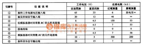
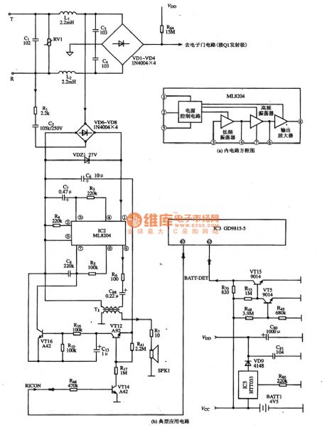
The ML8204 is designed as one kind of electronic bell integrated circuit, and it can be used in the communication equipments as the ring, such as the cordless telephone and the corded phone.etc.
1.Features
The ML8204 has the ringing drive signal generation circuit and the ring signal drive circuit.etc, and it produces two alternate output audio electronic ringing. The internal circuit block diagram is as shown in figure (a). The pin functions and data is as shown in the table.
The pin functions and data of the ML8204
2.Typical application circuit
The typical application circuit of the ringing circuit which is composed of the ML8204 integrated circuit is as shown in the figure (b).
The typical application circuit of the ringing circuit which is composed of the ML8204 integrated circuit (View)
View full Circuit Diagram | Comments | Reading(1870)
Video monitor circuit
Published:2011/6/8 2:42:00 Author:Christina | Keyword: Video, monitor
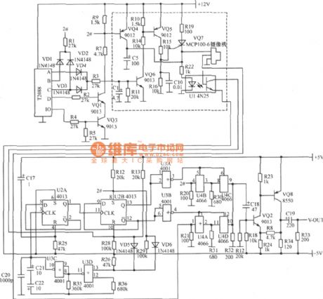
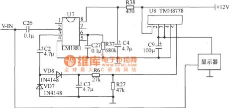
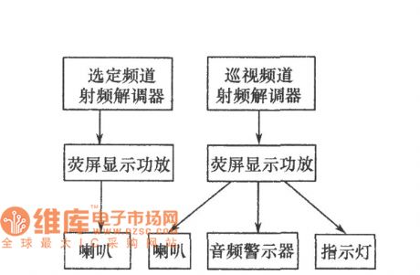
The monitor's wireless remote control circuit uses the T2078 receiving module, and it has the 100m four buttons launch mobile phone. The remote control mobile phone has four buttons, when you press button A, the number 1 camera starts working, the video signal is transmited to the displayer through the control circuit and the electric cable to show the situation of the monitoring point 1; when you press button B, the number 2 camera starts working and shows the situation of the monitoring point 2 on the displayer; when you press the button C, the number 1 and number 2 cameras work at the same time, the two channels of video signals were sent to the displayer respectively under the action of the video control circuit, the monitors alternately shows the situations of the monitoring point 1 and 2; when you press the button D, the cameras stop working.
1.Power supply
2.Camera shooting, video control and signal compensation circuit
3.Display control circuit
(View)
View full Circuit Diagram | Comments | Reading(1330)
power MOSFET isolated gate drive circuit
Published:2011/6/7 20:09:00 Author:John | Keyword: isolated gate
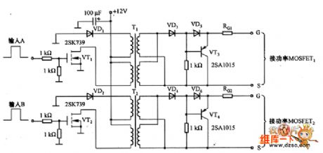
Power MOSFET isolated gate drive circuit is just as shown in the figure. In the circuit, pulse signals input to terminal A and B are from the switching power supply integrated controllers such as TL494 or UC3852. T1 and T2 are pulse transformers, which aim to provide high-low voltage isolation and enhance the ability of anti-noise. Therefore, high power switching circuit can work reliably. Circuit’s duty cycle can be adjusted with a range from 0% to 45%. Switching characteristics of power MOSFET are quite related to the ability of the gate drive. VT3 and VT4 here all use PNP-type transistors in order to rapidly discharge accumulation of charge between the power MOSFET's gate and source pole , thereby reducing its on / off delay time.
(View)
View full Circuit Diagram | Comments | Reading(4315)
LM1875 current feedback BTL circuit
Published:2011/6/3 20:12:00 Author:chopper | Keyword: current feedback, BTL

View full Circuit Diagram | Comments | Reading(3330)
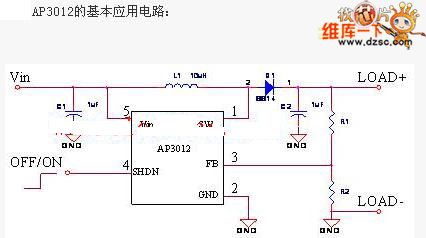
AP3012 positive-negative power supply circuit
Published:2011/6/6 9:54:00 Author:chopper | Keyword: positive-negative power supply
View full Circuit Diagram | Comments | Reading(1202)
The week digit displayer circuit
Published:2011/6/7 22:28:00 Author:qqtang | Keyword: digit displayer
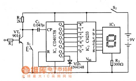
The week digit display circuitThe circuit of the week digit display circuit is in the figure, of which IC1 is a decimal counter/distributor, IC2 is a special integrated circuit CH233 of TV channels, and it can drive LED digital displayers directly and make it display the numbers of 1-8. The clock control signals in the circuit is from the PM terminal of large crystal clock, it is outputting a converting pulse at o'clock every night. When the pulse signal is amplified by VT1, it is delivered to the CP terminal of IC1, by every input pulse, the high LEV of IC1 Qo-Q7 output terminal moves in turn.
(View)
View full Circuit Diagram | Comments | Reading(656)
| Pages:254/312 At 20241242243244245246247248249250251252253254255256257258259260Under 20 |
Circuit Categories
power supply circuit
Amplifier Circuit
Basic Circuit
LED and Light Circuit
Sensor Circuit
Signal Processing
Electrical Equipment Circuit
Control Circuit
Remote Control Circuit
A/D-D/A Converter Circuit
Audio Circuit
Measuring and Test Circuit
Communication Circuit
Computer-Related Circuit
555 Circuit
Automotive Circuit
Repairing Circuit