
Control Circuit
Index 256
Xunda MB-DS elevator slowdown and door region switch circuit
Published:2011/6/2 1:33:00 Author:TaoXi | Keyword: Xunda, elevator, slowdown, door region, switch circuit
Xunda MB-DS elevator slowdown and door region switch circuit (View)
View full Circuit Diagram | Comments | Reading(578)
Xunda VFP door-opening circuit
Published:2011/6/2 1:44:00 Author:TaoXi | Keyword: Xunda, door-opening
Xunda VFP door-opening circuit (View)
View full Circuit Diagram | Comments | Reading(673)
Single phase electromotor thyristor stepless speed regulation circuit
Published:2011/5/26 8:43:00 Author:Christina | Keyword: Single phase, electromotor, thyristor, stepless, speed regulation
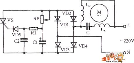
As the figure shows, the adjusting potentiometer RP can adjust the conduction angle of the thyristor to change the output voltage, so it achieves the purpose of the electromotor revolving speed stepless adjusting. If the RP resistance value is small, the VS conduction angle is big, the output voltage is high, so the electromotor revolving speed is high; on the contrary, if the RP resistance value is big, the electromotor revolving speed is low.
(View)
View full Circuit Diagram | Comments | Reading(902)
Winding rotor electric motor reverse connection braking circuit
Published:2011/5/29 22:41:00 Author:Christina | Keyword: Winding, rotor, electric motor, reverse connection, braking circuit
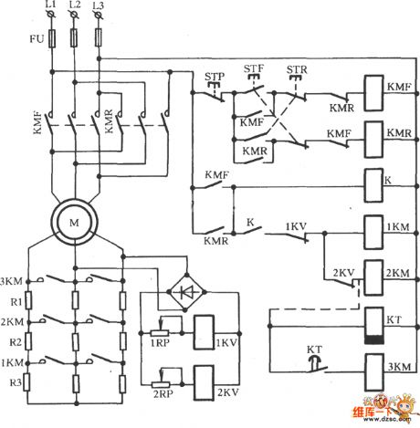
The Winding rotor electric motor reverse connection braking circuit is as shown:
(View)
View full Circuit Diagram | Comments | Reading(2404)
historical relic anti-thief alarm circuit
Published:2011/6/1 20:21:00 Author:Christina | Keyword: historical relic, anti-thief, alarm circuit
historical relic anti-thief alarm circuit (View)
View full Circuit Diagram | Comments | Reading(487)
Heat release electricity infrared detector alarm circuit
Published:2011/6/1 20:18:00 Author:Christina | Keyword: Heat release, electricity, infrared detector, alarm circuit
Heat release electricity infrared detector alarm circuit (View)
View full Circuit Diagram | Comments | Reading(510)
Heat release electricity infrared control electronic dog circuit
Published:2011/6/1 20:19:00 Author:Christina | Keyword: Heat release, electricity, infrared control, electronic dog
Heat release electricity infrared control electronic dog circuit (View)
View full Circuit Diagram | Comments | Reading(486)
human body control electric fan circuit
Published:2011/6/1 20:20:00 Author:Christina | Keyword: human body, control, electric fan
human body control electric fan circuit (View)
View full Circuit Diagram | Comments | Reading(579)
Motor protector circuit diagarm 5
Published:2011/6/1 20:02:00 Author:Lucas | Keyword: Motor protector
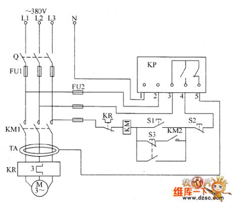
The motor protector circuit is composed of the ring current transformer TA, protection relay KP, start button S1, stop button S2, inching button S3, AC contactor KM and thermal relay KR and other components, and the circuit is shown as the FU1. Turning on the start button S1 will make KM get power and lock-hold, and the motor M will get power and operate; if pressing the inching button KR53 will make the M get power and operate. M will be turned off after A3 being reset. When one phase of the three-phase AC power supply open occurs phase, AC power contactor KM will be released, and the motor M stops to protect the motor and prevent their damage from phase running. When the motor M is over-current or overload, thermal relay KR operates to make the KM release and M stop.
(View)
View full Circuit Diagram | Comments | Reading(2224)
Motor protector circuit diagarm 4
Published:2011/6/1 20:07:00 Author:Lucas | Keyword: Motor protector
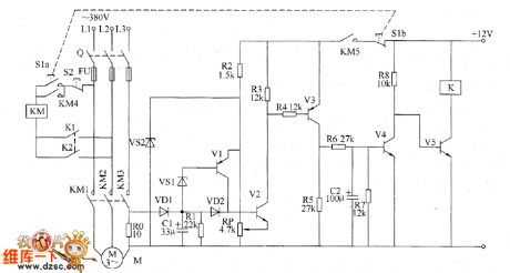
The motor protector circuit is composed of the current detection control circuit and delay control circuit, and the circuit is shown as the chart. Current detection control circuit is composed of the resistors R0 ~ R5, transistors V1 ~ 171VJ, capacitor C1, diodes VD1 and VD2, Zener diode VS1 and VS2. Delay control circuit consists of resistors R6 ~ R8, capacitor C2, transistors V4, V5 and relay Κ. S1 is the start button, S2 is the stop button, KM is the AC contactor. R0 selects 20W wire wound resistor; R1 ~ R8 select 1/4W metal film resistors. RP uses film variable resistor. C1 and C2 select aluminum electrolytic capacitors with the voltage above 10V. VD1 and VD2 use 1N4007 silicon rectifier diodes. VS1 and VS2 use 1W silicon Zener diodes.
(View)
View full Circuit Diagram | Comments | Reading(820)
The motor protector circuit diagram 1
Published:2011/6/1 7:14:00 Author:Lucas | Keyword: motor protector
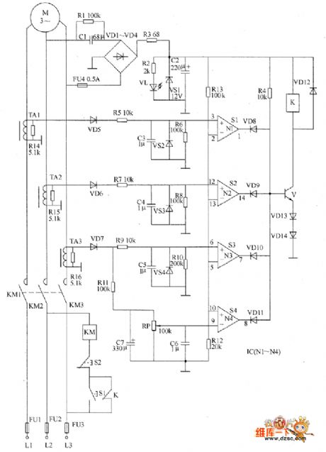
The motor protection circuit is composed of the power supply circuit, current detection circuit and protection control circuit, and the circuit is shown as the chart. Power supply circuit consists of capacitors C1, C2, resistors R1 ~ R3, rectifier diodes VD1 ~ VD4, Zener diode VS1 and power indicator LED VL. Current detection circuit is composed of the current transformers TA1 ~ TA3, resistors R5 ~ R11, R14 ~ R16, diodes VD5 ~ VD7, voltage regulator diodes VS2 ~ VS4, potentiometer RP, capacitors C3 ~ C7 and so on. Protection control circuit is composed of the operational amplifier integrated circuit IC (N1 ~ N4), resistors M, R12, R13, diodes VD8 ~ VD14, transistor V, relays K, AC contactor KM, start button S1, stop button S2 and so on.
(View)
View full Circuit Diagram | Comments | Reading(826)
The motor protector circuit diagram 2
Published:2011/6/1 7:19:00 Author:Lucas | Keyword: motor protector
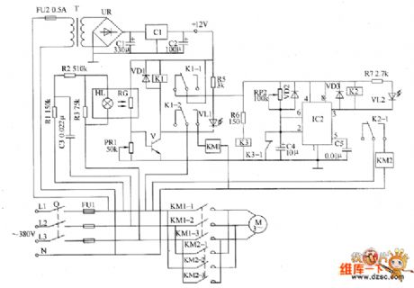
The motor protection circuit is composed of the DC power supply circuit, phase sequence detection circuit, sampling control circuit and automatic commutation circuit, and the circuit is shown as the chart. DC power supply circuit is composed of the fuse FU2, power transformer T, bridge rectifier UR, filter capacitors C1, C2, and three-terminal voltage regulator integrated circuit IC1. Phase sequence detection circuit is composed of the capacitor C3, resistors R1 ~ R3 and indicator light HL. Sampling control circuit consists of the photosensitive resistor RC, potentiometer RP1, transistor V, relay K1, diode VD1, resistor R5, LED VL1 and AC contactor KM1 and so on. R1 ~ R5 and R7 use 1/4W carbon film resistors or metal film resistors; R6 uses 1/2W metal film resistor.
(View)
View full Circuit Diagram | Comments | Reading(1485)
555 gas stove flameout sound & light alarm circuit
Published:2011/6/1 2:05:00 Author:TaoXi | Keyword: 555, gas stove, flameout, sound, light, alarm circuit
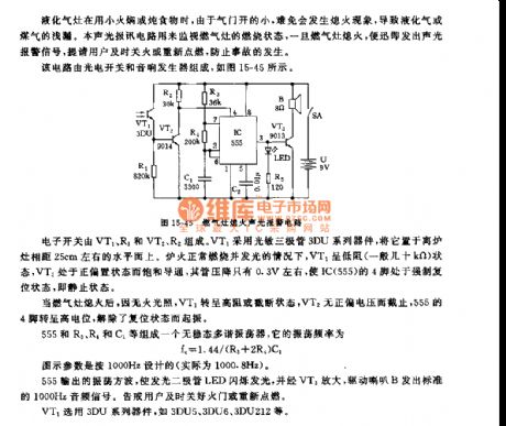
The electronic switch is composed of the VT1,R1 and VT2,R2. VT1 uses the phototransistor 3DU series devices, you need to put it on the horizontal plane that is about 25cm away from the stove. When the fire is normal, the VT1 is in the low resistance state, the VT2 is in the positive bias state, the pipe pressure drop is only about 0.3V, this makes the pin-4 of IC(555) in the state of forced reset -- the quiescent state.
The astable multivibrator is composed of the 555 and R3,R4,C1.etc, the oscillation frequency fc=1.44/(R3+2R4)C1. The parameters are designed according to 1000Hz.
VT1 uses the 3DU series devices such as the 3DU5, 3DU6, 3DU212.etc.
(View)
View full Circuit Diagram | Comments | Reading(645)
555 automatic home appliance protector circuit
Published:2011/6/1 2:32:00 Author:TaoXi | Keyword: 555, automatic, home appliance, protector
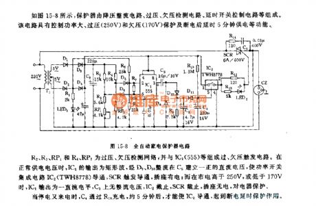
As the figure 15-8 shows, the protector is composed of the step-down rectifier circuit, the over-voltage under-voltage detection circuit and the delay switch control circuit. This circuit has some points of features such as the large power control, over-voltage (250V) and under-voltage (170V) protection , and the 5 minutes power-off delay.
The over-voltage under-voltage detection circuit is composed of the R2,R3,RP1,R4 and RP2, and the over-voltage under-voltage trigger circuit is composed of the over-voltage under-voltage detection circuit and the IC1(555). In the power supply voltage is normal, the IC1 outputs the rectangular wave, this wave is rectified by D9,D10, then establish the positive DC voltage on C5 to conduct the power switch integrated circuit IC2 (TWH8778), then the SCR is in the state of trigger conduction, the socket has the electricity.
(View)
View full Circuit Diagram | Comments | Reading(886)
555 sound control lighting electronic wall clock circuit
Published:2011/6/1 4:04:00 Author:TaoXi | Keyword: 555, sound control, lighting, electronic, wall clock
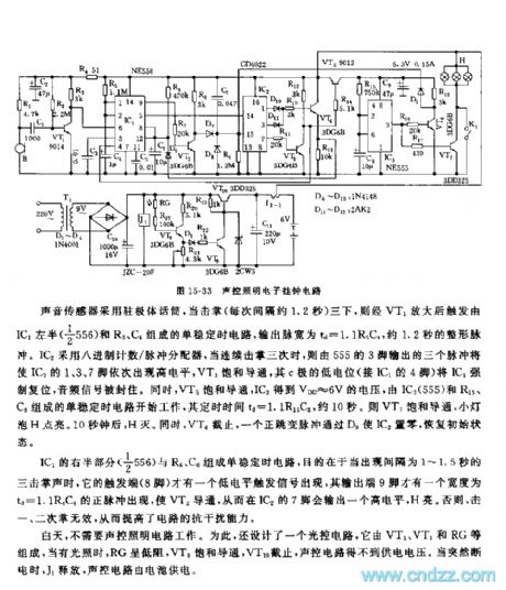
As the figure 15-33 shows, the circuit is composed of the voice sensor, the monostable trigger, the counter and the timing circuit.etc.
The voice sensor uses the electret condenser microphone, when you clap three times, the sound will be amplified by VT1, then triggers the monostable timing circuit which is composed of the left part (1/2 56) of the IC1 and the R5, C4, the output pulse-width td=1.1R5C4, it is about 1.2s. The IC2 uses the octonary number system count/pulse dispenser, when you clap three times, the pin-3 of 555 will output three pulses to make the pin-1, pin-3, pin-7 of IC2 have the high electrical level one by one, the VT3 conducts, the low potential of the c electrode resets the IC1, the audio signal is sealed.
(View)
View full Circuit Diagram | Comments | Reading(883)
555 electric rice cooker automatic controller circuit
Published:2011/6/1 19:10:00 Author:TaoXi | Keyword: 555, electric, rice cooker, automatic controller
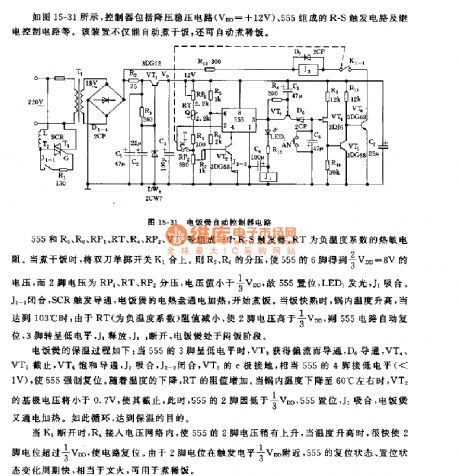
As the figure 15-31 shows, the controller is composed of the step-down voltage circuit (VDD=+12V), the R-S trigger circuit which is composed of 555 and the relay control circuit.etc.
The R-S trigger is composed of the 555 and R5, R6, RP1, RT, R4, RP2, VT2. RT is the negative temperature coefficient thermistor. When the cooker is cooking the dry rice, the two-knife single-throw switch K1 closes. So the separate voltages of R5 and R6 make the pin-6 of 555 gets the voltage of 2/3VDD=8V, the voltage of pin-2 is the separate voltage of RP1, RT, RP2, the voltage value is less than 1/3VDD, so 555 sets, LED1 turns on and J1 closes.
(View)
View full Circuit Diagram | Comments | Reading(945)
555 safe and reliable intermittent electric heating control circuit
Published:2011/5/30 18:41:00 Author:TaoXi | Keyword: 555, safe, reliable, intermittent, electric heating, control circuit
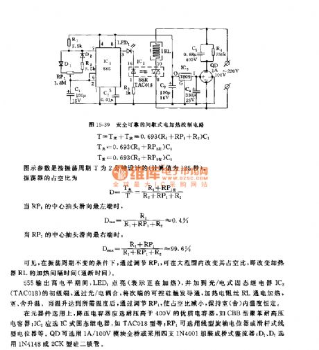
This heating circuit uses the light/electric type solid-state relay and it is composed of the step-down rectifier circuit, the duty ratio adjustable multivibrator and the solid-state relay, as the figure 15-39 shows.
The step-down rectifier circuit is composed of the buck capacitor C5, the full bridge rectifier QD and the filter capacitor C4, and it is stabilized by the three ports stabilizer IC2(7809), then it outputs the voltage of +9V to supply power to the control circuit.
The heating circuit uses the time base circuit 555 as the core, the duty ratio adjustable low-frequency multivibrator is composed of the 555 and R1,R2,RP1,D1,D2, the oscillation period is the fixed value, but the duty ratio can be adjusted by RP1.
(View)
View full Circuit Diagram | Comments | Reading(824)
555 safe iron frame circuit
Published:2011/5/30 18:53:00 Author:TaoXi | Keyword: 555, safe, iron, frame
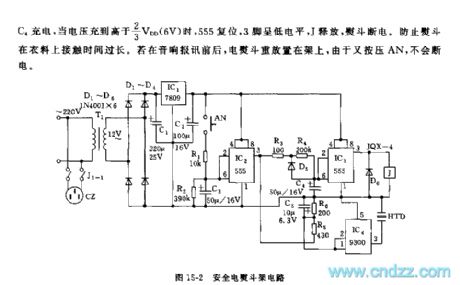
As the figure 15-2 shows, the circuit is composed of the step-down voltage rectifying circuit, the timer control circuit and the audio circuit.etc. When the electric iron is on the frame, the weight of iron presses the button AN, so IC2's trigger port pin-6 gets the partial voltage of R1 and R2, and this voltage is higher than 2/3VDD trigger electrical level, 555 resets, pin-3 has the low electrical level. IC3 is set because pin-2 has the low electrical level, pin-3 has the high electrical level, the relay J closes, and also the J1-1 twin contact points, so the electric iron has power to heat. When you pick up the iron, the C3 which has be charged discharges through R2, when the voltage is lower than pin-2's trigger electrical level 1/3VDD, 555 sets, pin-3 has the high electrical level.
(View)
View full Circuit Diagram | Comments | Reading(1807)
555 multi-function digital control lock circuit
Published:2011/6/1 4:28:00 Author:TaoXi | Keyword: 555, multi-function, digital control, lock circuit
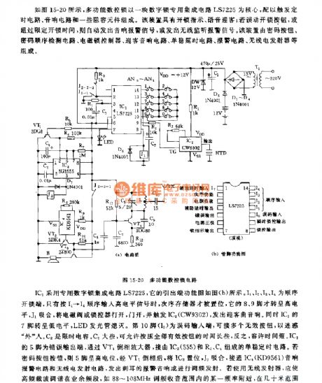
As the figure 15-20 shows, the multi-function digital control lock uses the digital control lock ASIC LS7225 as the core, and this control lock circuit is composed of the trigger timing circuit, the audio circuit and some RC components.
The IC1 uses the digital control lock ASIC LS7225, it's output port function diagram is as shown in figure (b). If you press the wrong password, the 555 has the high electric potential, and this electric potential is paraphased by VT1 to set the IC3, the J2 closes to open the IC4(KD9561) sound alarm circuit and the radio transmitting circuit, they send out the ear-piercing alarm or transmit the FM. If you use the wireless receiver, you should turn the high-frequency carrier wave in the amateur band such as 88~108MHz.
(View)
View full Circuit Diagram | Comments | Reading(676)
555 electronic cane circuit
Published:2011/6/1 18:59:00 Author:TaoXi | Keyword: 555, electronic cane
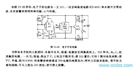
As the figure 15-38 shows, the electronic cane circuit is composed of a 555 circuit, a audio integrated circuit KD-9561 and the mercury switch.etc. It has two functions: alarm and lighting, it is small and exquisite.
When people with this electronic cane fall down, the mercury switch K1 opens, the power supply adds to the two integrated blocks. The trigger circuit is composed of the 555 and R1, R2, C1. Once the K1 opens, because the C1's voltage can not be changed, so the 555 sets, it's pin-7 has the high resistance to conduct VT1, so the alarm sound of the KD-9561 is sent out by the YD electromagnetic signal response device to call people for help.
(View)
View full Circuit Diagram | Comments | Reading(669)
| Pages:256/312 At 20241242243244245246247248249250251252253254255256257258259260Under 20 |
Circuit Categories
power supply circuit
Amplifier Circuit
Basic Circuit
LED and Light Circuit
Sensor Circuit
Signal Processing
Electrical Equipment Circuit
Control Circuit
Remote Control Circuit
A/D-D/A Converter Circuit
Audio Circuit
Measuring and Test Circuit
Communication Circuit
Computer-Related Circuit
555 Circuit
Automotive Circuit
Repairing Circuit