
Control Circuit
Index 252
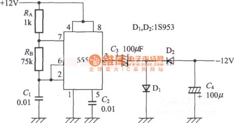
Negative Voltage Generated Circuit Composed of Timer IC555
Published:2011/5/25 4:45:00 Author:Joyce | Keyword: Negative Voltage, Generated , Timer IC555
View full Circuit Diagram | Comments | Reading(719)
Simulated Pendulum Circuit Composed of CD4017
Published:2011/6/2 9:58:00 Author:Joyce | Keyword: Simulated, Pendulum , CD4017
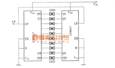
Making use of the characteristics of the ten output ends of CD4017 that they will move as being input with clock pulse, it is connected with a luminous diode in each of its output ends. The movement of output position will make the light emitting diode function, thus forming a simulated pendulum circuit. If it is installed in digital electronic clocks, it can not only make the clock work, but it can serve as a kind of adornment. The composition of the circuit is shown in the graph.
(View)
View full Circuit Diagram | Comments | Reading(1404)
MC33260 power factor regulating integrated circuit
Published:2011/6/9 0:55:00 Author:Christina | Keyword: power factor, regulating, integrated circuit
The MC33260 is designed as one kind of power factor regulating integrated circuit that is produced by the MOTOROLA company, and it can be used in wide range of applications such as the rear projection color TVs and the LCD color TVs.
1.Features
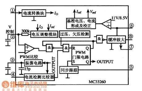
The MC33260 integrated circuit is composed of the reference voltage and current formation and correction circuit, the over-voltage and undervoltage detection circuit, the oscilation circuit, the current detection comparator, the current converter circuit, the voltage regulating circuit, the PWM comparative circuit, the synchronization tracking circuit, the buffer amplifier and other auxiliary circuit, the internal circuit block diagram is as shown in figure 9.
The internal circuit block diagram of the MC33260
2.Pin functions and data
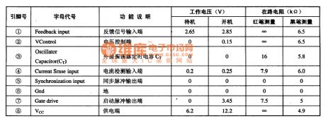
The MC33260 is in the 8-pin double-row DIP plastic apckage, the pin functions and data is as shown in the table, this data is measured from the ChangHong JingXian rear projection color TV.
The pin functions and data of the MC33260
(View)
View full Circuit Diagram | Comments | Reading(863)
Amplifier tube protector circuit
Published:2011/6/8 6:32:00 Author:Christina | Keyword: Amplifier tube, protector
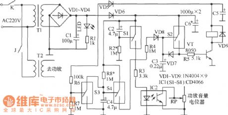
The amplifier tube protector circuit is as shown in the figure.
Working principle: K is the power supply switch, T1 is the small control power transformer, T2 is the amplifier power transformer. The IC1(S1-S4) is the four-way analog switch CD4066. When the circuit is booting, you need to close K1, so the C1 gets the 12V DC current. At this time the S3 conducts because the control port has the high electrical level, if you make the control port of S4 to have the low electrical level, the S4 will cut off. The voltage of C2 can not be changed, so the S1 conducts because of the control port has the high electrical level, the optocoupler IC2's LED turns on, the photodiode conducts to make the amplifier volume potentiometer's output audio signal shorted to ground. After the S1 is conducted, C3 charges for few tenths second, the S2 conducts, then the VT conduct, the relay J closes to connect the amplifier power supply. (View)
View full Circuit Diagram | Comments | Reading(564)
MC33033 brushless DC motor drive control integrated circuit
Published:2011/6/9 1:07:00 Author:Christina | Keyword: brushless, DC, motor, drive control, integrated circuit

The MC33033 is designed as one kind of brushless DC motor drive control integrated circuit that is produced by the MOTOROLA company, it can be used in the electric bicycle and other occasions that need to drive the brushless DC motor.
1.Features
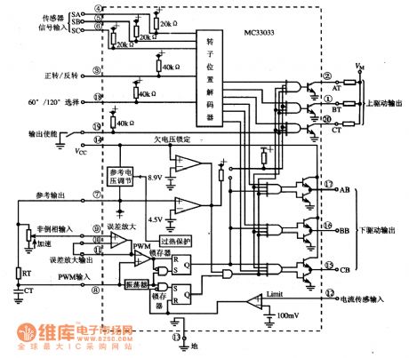
The MC33033 is composed of the rotor position decoder, the reference voltage regulator, the oscillator, the error amplifier, the pulse width modulation comparator, the current limiting protection circuit, the under voltage locking circuit, the overheat protection circuit and the drive output circuit.etc.
2.Pin functions and data
The MC33033 is in the dual-row 20-pin package, the pin functions and data is as shown in the table.
The pin functions and data of the MC33033
3.The internal circuit block diagram and the typical application circuit
The internal circuit block diagram and the typical application circuit of the MC33033 is as shown.
The internal circuit block diagram and the typical application circuit of the MC33033 (View)
View full Circuit Diagram | Comments | Reading(3622)
TTS-200 temperature control thyristor basic application circuit
Published:2011/6/9 1:51:00 Author:Christina | Keyword: temperature control, thyristor, basic application
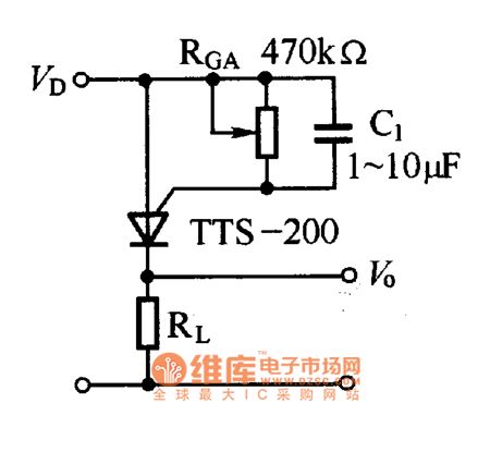
The basic application circuit of the temperature control thyristor is as shown in the figure. The RcA is the switch temperature control resistance, you can get different switch temperature by selecting different resistance of the RGA. VD is the operating voltage. When the temperature is lower than the switch temperature, the temperature control thyristor is in the cut-off state, VD port outputs the low electrical level; when the temperature reaches or exceeds the switch temperature, the temperature control thyristor conducts, the VD port outputs the high electrical level. It should be noted that the operating voltage VD has the relationship with the switch temperature, in order to ensure the stability of the temperature switch, VD needs to use the regulation measures.
Figure: The TTS-200 temperature control thyristor basic application circuit (View)
View full Circuit Diagram | Comments | Reading(789)
MC3357 small power frequency modulation intermediate frequency integrated circuit
Published:2011/6/9 2:03:00 Author:Christina | Keyword: small power, frequency, modulation, intermediate frequency, integrated circuit
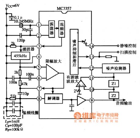
The MC3357 is designed as one kind of small power frequency modulation intermediate frequency integrated circuit that is produced by the MOTOROLA company, and it can be used in the FM amplifier circuit of the FM duplex communication equipments.
1.Features
The MC3357 is composed of the oscillator circuit, the mixer circuit, the noise suppression and hysteresis circuit, the active filter amplifier circuit, the amplitude limit amplifier circuit, the demodulator circuit and other subsidiary function circuits.
2.Pin functions and data
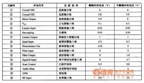
The MC3357 has two kinds of package: one is the 16-pin dual-row DIP package; another is the 16-pin small SMD package that can be used in the surface installation technology, the pin functions and data is as shown in the table.
The pin functions and data of the MC3357
3.Typical application circuit
The internal circuit block diagram and the typical application circuit of the MC3357 is as shown in the figure.
The internal circuit block diagram and the typical application circuit of the MC3357 (View)
View full Circuit Diagram | Comments | Reading(1328)
The music fancy lantern controller circuit
Published:2011/6/2 8:17:00 Author:Seven | Keyword: music fancy lantern, controller circuit
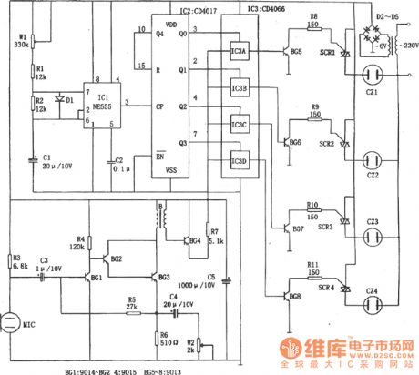
See as the following figure, this is a music fancy lantern controller circuit. The controller consists of sound/power switch and amplifier circuit, clock pulse generator, counting circuit and control circuit, etc. The microphone MIC switch sound signal into power signal, and then the signal is added to 4-channel analog switch CD4066(IC3) after it has been magnified by BG1~BG3. The clock pulse generator consists of IC1(555), W1, R1, R2, D1, C1 and so on, the period of signal generating is T=0.693(Rw1+R1+R2)C1, the period corresponding to the figured parameter ranges 0.5~5s, of which the 3-pin output of 555 is added to IC2 as the CP pulse.
(View)
View full Circuit Diagram | Comments | Reading(687)
active filter circuit
Published:2011/6/3 19:56:00 Author:chopper | Keyword: active filter
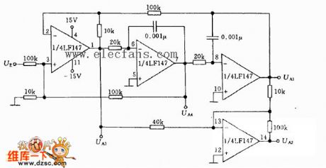
Its core frequency fo=3.4kHz,notch frequency fc=9.5kHz,quality factor Q=3.4.AS for high frequency filter,coefficient of transmission is 0.1;as for band-pass filter,the coefficient is 1;as for low frequency filter,the coefficient is 1;as for low amplitude filter,the coefficient is 1; as for notch filter,the the coefficient is 10.foQ≤200KHz.When output string signal is within 10V,its highest frequency is not more than 200KHz.
(View)
View full Circuit Diagram | Comments | Reading(671)
the principle of zero-crossing comparison and phase comparison circuit
Published:2011/6/8 20:32:00 Author:chopper | Keyword: principle, zero-crossing comparison, phase comparison
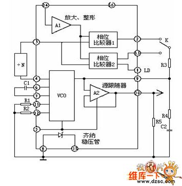
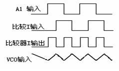
The phase-locked loop CD4046 in common usage of integrated circuit is a universal CMOS PLL integrated circuit.Its feature is that its supply voltage ranges widely(3V-18V)and the input impedance is high(about 100MΩ),dynamic power consumption is low.When the core frequency f0 is 10KHZ,the power consumption is just 600μW and it is a micro-power module.The following picture is the pins arrangement of CD4046 and it adopts 16 feet dual inline type. The functions of pins is as follows.
(View)
View full Circuit Diagram | Comments | Reading(971)
The contactless fancy lantern controller circuit
Published:2011/6/2 8:30:00 Author:Seven | Keyword: contactless, fancy lantern
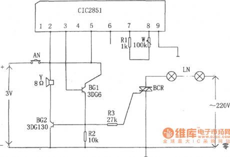
When the switch of AN is pressed, CIC2851 is triggered to work, the output terminal (3-pin) launches music signals. After the music signals are BG1 and BG2 is magnified, the loudspeaker makes music. In the meantime, the dual controllable silicon SCR is conducting and the fancy lantern is glowing with the change of the music. By adjusting W, the performing time of the circuit is changed, i.e the flashing time of the fancy lantern is changed.
(View)
View full Circuit Diagram | Comments | Reading(583)
AP3012 positive and negative voltage production circuit
Published:2011/6/8 7:27:00 Author:chopper | Keyword: positive, negative, voltage production

View full Circuit Diagram | Comments | Reading(1341)
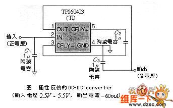
DC-DC with polarity inversion circuit
Published:2011/6/6 9:58:00 Author:chopper | Keyword: DC-DC, polarity inversion
View full Circuit Diagram | Comments | Reading(693)
electronic filter circuit
Published:2011/6/8 6:48:00 Author:chopper | Keyword: electronic filter
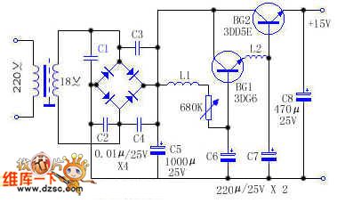
BG1 and BG2 form mulriple pipe.This circuit adds the filter element to the base of mulriple pipe which is different from others. The magnification coefficient of mulriple pipe β=β1•β2,so the filtering effect obtained from BG2 emitter is β1 times over L1 and C6,which equals that the big capacitance and inductance are added to the circuit.The most of hum in the circuit is restrained.And because the circuit adds L2 and C7 as well,their filtering effect was expanded β2 times by BG2,and leaches residual hum further.
(View)
View full Circuit Diagram | Comments | Reading(699)
Bandpass filter circuit
Published:2011/6/6 10:16:00 Author:chopper | Keyword: Bandpass filter
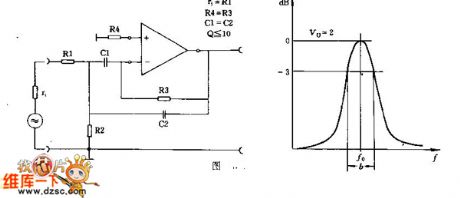
This circuit should determine the value of the R1 aforehand which is similar to the signal source resistance r1/ The principle of parameter selection is R4 = R3,C1 equals to C2 approximately,and Q equals to or lesser than R1,500K>R>1K,0.5uF>C>200pF.
(View)
View full Circuit Diagram | Comments | Reading(632)
The beverage temperature controller circuit of fast heating and cooling
Published:2011/6/9 21:56:00 Author:qqtang | Keyword: beverage temperature controller, fast heating and cooling
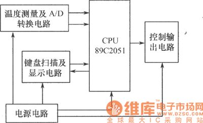
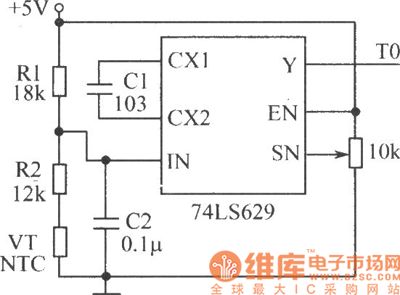
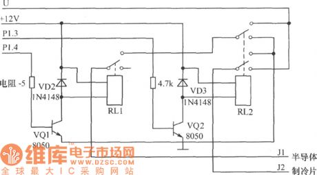
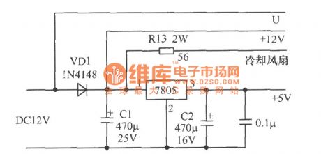
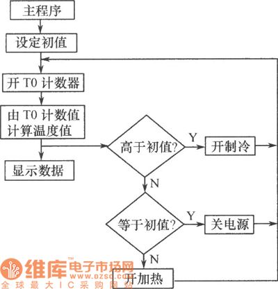
The hardware of the temperature control system consists of temperature measuring and A/D switch circuit, signal test and process circuit, key scanning and displaying circuit, control output circuit and power supply circuit and so on. The circuit is shown in the figure.(1) signal test and process circuit: the core of the temperature controller is the high quality-price ratio 8-bit micro-controller AT89C2051, which is used to complete the data measuring and processing, so that it can fulfill the measure and control function of the beverage temperature.(2) temperature measuring and A/D switch circuit
(View)
View full Circuit Diagram | Comments | Reading(884)
The schematic diagram of LCD digital displayer construction
Published:2011/6/9 22:06:00 Author:qqtang | Keyword: schematic diagram, LCD digital displayer
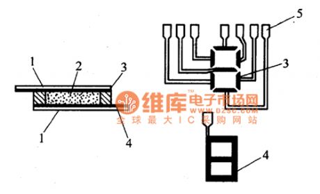
LCD displayer is also called LCD digital displayer, whose construction is shown in the figure. The main material of LCD displayer is liquid crystal(abbreviated as LC) which is a organic material, in certain temperatures, it not only has the mobility of the liquid, but also has the light character, its transparence changes with the electric field, magnetic field, light, temperature and other outside conditions. Therefore, under the effect of the logic circuit output signals, it can indicates some certain numbers. LCD displayer is a passive displaying element.
(View)
View full Circuit Diagram | Comments | Reading(1114)
The digital tachometer circuit
Published:2011/6/6 11:48:00 Author:qqtang | Keyword: digital tachometer
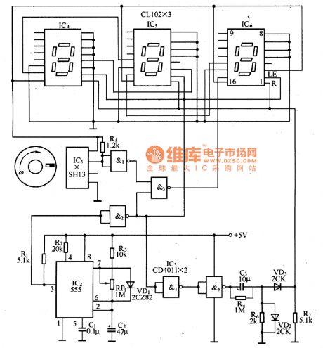
The circuit mainly consists of the magnetic disc with permanent magnet, Hall integrated sensor, strobing gate circuit, time-based signal circuit, power supply and digital display circuit, etc. The counting and digital display circuit are fixed with CMOS-LED digital display component CLIO2, and it can count and displaying digits. The input axis of the rotating disc and the rotating axis under test are connected, when the axis is rotating, the rotating disc is running with it. When the little permanent magnet crosses the Hall integrated circuit IC1, IC1 will switch the magnetic signal into the rotating speed signals.
(View)
View full Circuit Diagram | Comments | Reading(5345)
the digital stopwatch circuit
Published:2011/6/6 12:04:00 Author:qqtang | Keyword: digital stopwatch
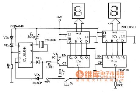
In the figure is the digital stop watch circuit. 5G5544(IC1) in the figure is a quartz integrated circuit, and it works as the second generator. 5G5544 outputs a pulse that the period is 2s by the 3-pin and the 5-pin, VD3,VD4 and VT1 consist a LEV converting circuit, and the second signal output is got. CD4518(IC2) contains two same decimal calculators, so binary counting can be formed, if more bit counting is needed, multi-connection can be done. CD4511(IC3、1C4) is the BCD-7 decoding/drive integrated circuit.
(View)
View full Circuit Diagram | Comments | Reading(4132)
counter circuit
Published:2011/6/8 20:51:00 Author:chopper | Keyword: counter
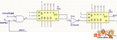
Measuring phase angle adopts hardware counting mode instead of singlechip direct counting mode.Because hardware counting mode can improve the precision.We make 256 scale successive carry counting mode by using two pieces of 74HC161 in series.The external frequency reference selects a high-speed pulse generated by 10MHz active crystal oscillator to count the width of signal Fi output by phase-locked loop.Therefore,it can make the measuring absolute error of transadmittance angle less than 5% of theoretic calculation.The principle of circuit is as follows.
(View)
View full Circuit Diagram | Comments | Reading(633)
| Pages:252/312 At 20241242243244245246247248249250251252253254255256257258259260Under 20 |
Circuit Categories
power supply circuit
Amplifier Circuit
Basic Circuit
LED and Light Circuit
Sensor Circuit
Signal Processing
Electrical Equipment Circuit
Control Circuit
Remote Control Circuit
A/D-D/A Converter Circuit
Audio Circuit
Measuring and Test Circuit
Communication Circuit
Computer-Related Circuit
555 Circuit
Automotive Circuit
Repairing Circuit