
Control Circuit
Index 242
The Isuzu truck instrument,alarm indicator and lighting lamp circuit
Published:2011/6/25 20:03:00 Author:qqtang | Keyword: Isuzu, alarm indicator, lighting lamp
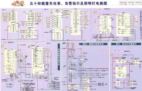
The Isuzu truck instrument,alarm indicator and lighting lamp circuit is shown as above.
(View)
View full Circuit Diagram | Comments | Reading(1029)
The gas-fog alarm circuit of dual-way thyristors
Published:2011/6/25 21:45:00 Author:qqtang | Keyword: gas-fog alarm, dual-way thyristors
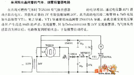
The gas-fog alarm circuit of dual-way thyristors When there is the combustible, the conductance of the TGS308 gas sensor is increasing, and it picks out the voltage with the help of potentiometer RP1, the value of the voltage is from 3V to 20V. The raised voltage is then added on transistor VT1 by the diode and the 4.7kΩ resistor, so VT1 is conducting, which makes the dual thyristor 2N6070A conducting. Because of what described above, the full-wave AC voltage pushes H to generate the sound of 90dB, fulfilling the alarm. H is the 20V AC alarm of Deltal6003168.
(View)
View full Circuit Diagram | Comments | Reading(526)
The switching circuit with self-hold function
Published:2011/6/20 8:51:00 Author:Nancy | Keyword: self-hold function, switching circuit
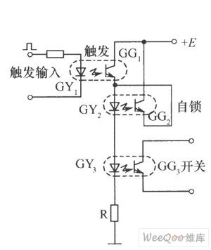
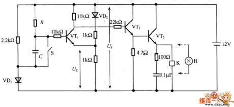
The switching circuit with self-hold function is shown as above. The three photocouplers serve as trigger, self-hold and switch respectively. When there is a start trigger signal added to GY, GG1 conducts, the GY2 and GY3 glow with current flowing through to make GG2 and OG3 conduct. When the trigger signal disappears, GY1 doesn't glow to make GG1 cut off, but GG2 has been conducted, the current of GY2 and GY3 is provided by GG2 path, which is equivalent to saying that the switch continues to connect and the circuit can't recover until the power supply E disappears. (View)
View full Circuit Diagram | Comments | Reading(1634)
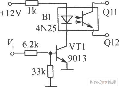
The switching circuit composed by photocoupler
Published:2011/6/20 8:35:00 Author:Nancy | Keyword: photocoupler, switching circuit
View full Circuit Diagram | Comments | Reading(724)
The transistor ionization alarm circuit
Published:2011/6/24 22:09:00 Author:qqtang | Keyword: transistor, ionization alarm
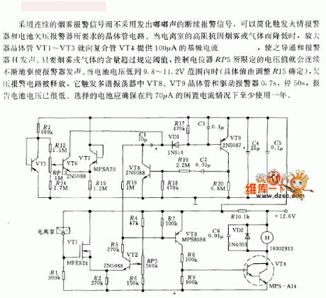
It could simplify the transistor circuit of trigger fire alarm and battery low voltage alarm by using continuous fog alarm signal but not the intermittent Beep sound alarm signal. When the impedance in the ionization room is dropping due to the fog or gas, the amplifier transistors VT1~VT3 will offer 100μA basic electrode current to the compound pipe VT4, which makes VT4 conducting and the alarm H generate sound. As the fog or gas content is higher than the regulated threshold value, the voltage limited by RP5 will push the alarm to make sounds.
(View)
View full Circuit Diagram | Comments | Reading(857)
The time delay circuit composed of transistors
Published:2011/6/24 22:41:00 Author:qqtang | Keyword: time delay, transistors
In the circuit is the time delay circuit composed of transistors, which is connected with the loading after the delayed time. According to the resistance of R and the comparing voltage UE change, the delayed time can be set. In the circuit, S is the charging switch of capacitor C, when S is closed, the electricity in C is released by S, which assures of the precise delayed time next time. VD1 and VD2 are used to reduce the effect of UBE on VT1. In the circuit, the loading current can only be 50mA or so, which can be expanded by switching VT3 into the Darlington transistor.
(View)
View full Circuit Diagram | Comments | Reading(701)
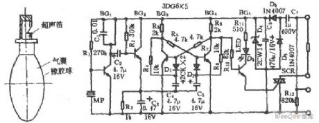
The ultrasonic moving alarm circuit
Published:2011/6/24 22:28:00 Author:qqtang | Keyword: ultrasonic, moving alarm
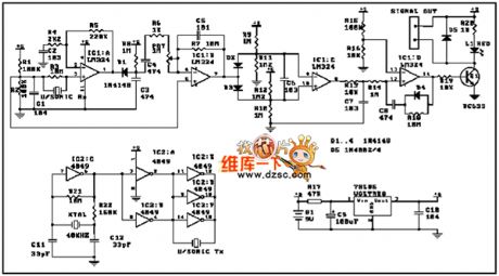
View full Circuit Diagram | Comments | Reading(729)
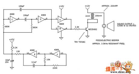
The 120db frequency sweeping alarm sound circuit
Published:2011/6/24 23:08:00 Author:qqtang | Keyword: frequency sweeping, alarm sound
View full Circuit Diagram | Comments | Reading(1067)
The dual-way transistor AC switch circuit of optical fiber control
Published:2011/6/25 1:09:00 Author:qqtang | Keyword: dual-way transistor, AC switch, optical fiber
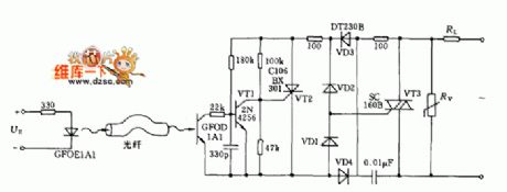
View full Circuit Diagram | Comments | Reading(646)
The semi-conductor analog switch circuit
Published:2011/6/24 23:05:00 Author:qqtang | Keyword: semi-conductor, analog switch
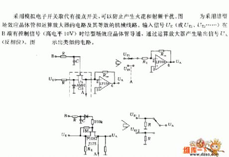
By replacing the connector switch with the analog electric switch, the spark and RF noise can be avoided. In the figure is the knot FET transistor, op-amp circuit and other equivalent mechanical circuit. When there is the control signal (the LEV is higher than 10V) of the input signal UE (or UE1, UE2 and so on) on B terminal, the op-amp generates the output signal UA(inverting phase). In Figure 2 is the circuit of the same type.
(View)
View full Circuit Diagram | Comments | Reading(659)
555 time relay circuit
Published:2011/6/20 8:46:00 Author:TaoXi | Keyword: 555, time relay
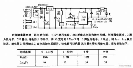
This circuit is composed of the +12V voltage stabilization circuit, the 555 monostable circuit and the relay control circuit, when the power is connected, pin-2 has the low level, the 555 sets, the relay J2 will not act, when the voltage of C2 is charged to 2VDD/3, the pin-3 has the low level, the J2 closes to connect the contact points J2-1 and J2-2. The NC contact point J1 of the relay J1 will cut off after the circuit got the power. This circuit can replace the JSJ1 transistor time relay. The timing parameters are as shown:
(View)
View full Circuit Diagram | Comments | Reading(673)
555 approach switch circuit
Published:2011/6/20 8:35:00 Author:TaoXi | Keyword: 555, approach, switch circuit
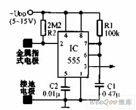
The approach switch circuit is the monostable trigger which is composed of the 555. The trigger port pin-2 of 555 is connected with the power supply voltage port through the high value resistance, it is in the standby state. When the human body approaches or touches the metal plate, the induction signal 555 is triggered to output a monostable pulse. The C2 can be used in the anti-disturbance filtering. This circuit can be used in the electrical equipments, the toys and the alarm circuits.
(View)
View full Circuit Diagram | Comments | Reading(665)
The dual-way converting switch typical circuit with lock
Published:2011/6/24 23:23:00 Author:qqtang | Keyword: dual-way, converting switch, typical circuit
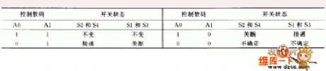
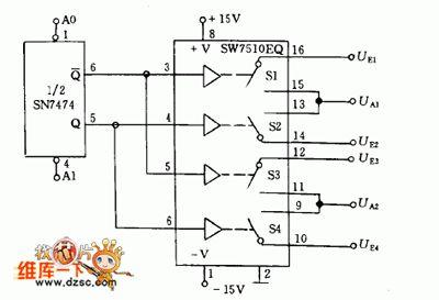
In the figure is circuit of the dual forward trigger SN7474 with presetting and clearance, and the analog switch SW7510EQ. Its control encoding and switch stage are shown in the table.
(View)
View full Circuit Diagram | Comments | Reading(884)
The fast speed analog switch circuit
Published:2011/6/25 1:21:00 Author:qqtang | Keyword: fast speed, analog switch
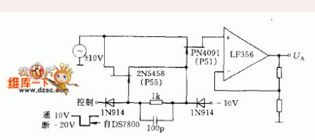
The we need to fast, exactly and reliably change or put through the high LEV, we can use the figured circuit (such as the digital, synchronized converter). The feedback net can output stable signals, which can offset the effect caused by the output change of circuit parameters. The DC input signals in the range of ±10V and the -20V DC voltage on the FET transistor grid work together, which makes the input channel blocked. The input channel is put through when FET transistor grid is +10V, and then the grid is output by the op-amp.
(View)
View full Circuit Diagram | Comments | Reading(775)
A touch switch circuit
Published:2011/6/25 1:26:00 Author:qqtang | Keyword: touch switch
The figured circuit just connects the touch board with the positive pole of the power supply, but not the earth. Therefore, its working principle and application condition haven't changed.
(View)
View full Circuit Diagram | Comments | Reading(650)
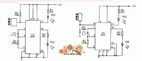
The wide range timing switch circuit
Published:2011/6/25 1:39:00 Author:qqtang | Keyword: wide range, timing switch
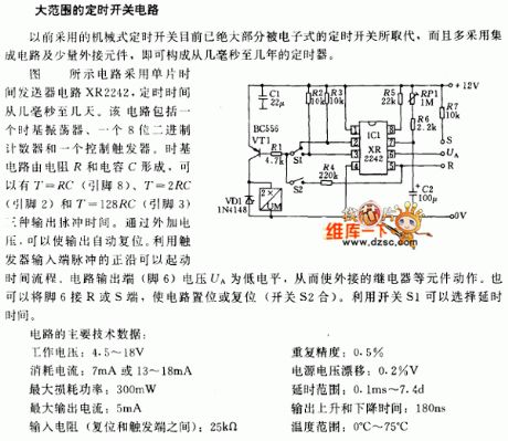
The traditional mechanical timing switches have almost been replaced by electric timing switch, and they are often the integrated circuit with a few external elements, i.e the components can compose a timer whose range is from several ms to several years. In the figure, the circuit is fixed with the single chip time deliver circuit XR2242, the time ranges from several ms to several years. The circuit consists of a time-base oscillator, a 8-bit binary counter and a control trigger. The time-base circuit consists of the resistor R and capacitor R, which has 3 output pulse times, they are T=RC(8-pin), T=2RC(2-pin) and T=128(3-pin). By adding an external voltage, the output can be reset.
(View)
View full Circuit Diagram | Comments | Reading(633)
The Mitsubishi auto escalator control circuit
Published:2011/6/25 4:55:00 Author:qqtang | Keyword: Mitsubishi, auto escalator
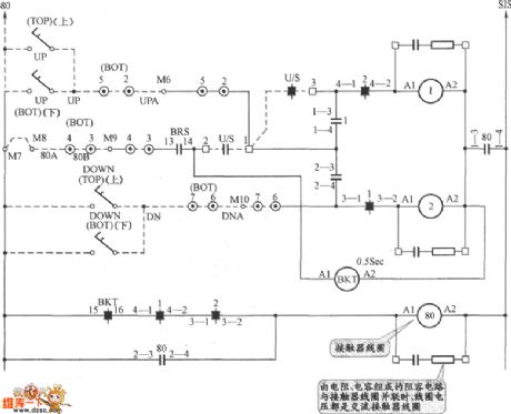
The Mitsubishi auto escalator control circuit is shown in the figure.
(View)
View full Circuit Diagram | Comments | Reading(3669)
The axis temperature alarm circuit
Published:2011/6/25 20:16:00 Author:qqtang | Keyword: axis, temperature alarm
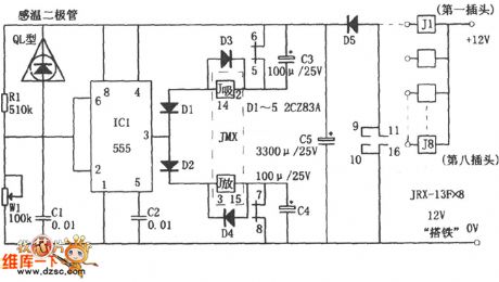
In the figure is the axis temperature alarm circuit. The alarm consists of the sensing component, time-base circuit IC1(555) and relays, etc. In this circuit, the sensing element is the temperature sensing diode(QL type), which is usually fixed in the axis box and installed on the circuit board by a self-closed plug. The temperature diode QL is in parallel connection with R1, when the axis is in a normal temperature, the resistor R1 and potentiometer W1 distribute the voltage, which make the 6-pin of 555 in a LEV which is lower than 1/3VDD(=4V)and the 3-pin output a high LEV. The corresponding pulse relay (the magnet maintaining relay) MX is in the releasing state.
(View)
View full Circuit Diagram | Comments | Reading(674)
The dual-way thyristor dimmer circuit
Published:2011/6/24 7:53:00 Author:Seven | Keyword: thyristor, dimmer
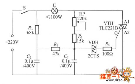
To solve the problem the lag and jump of the light, the figured dual-way thyristor dimmer circuit of dual time constants. In the circuit, we add a R3 and C2, they are the resistance and capacitance net, the reduced electricity of C1 can be compensated in time by C2, R2 and R3, therefore, the phenomena of lag and jump can be effectively reduced, at the same time, it expands the adjusting range of the minimum brightness of the light.
(View)
View full Circuit Diagram | Comments | Reading(1251)
Electric fan sub-ultrasonic remote control switch circuit
Published:2011/6/16 7:03:00 Author:TaoXi | Keyword: Electric fan, sub-ultrasonic, remote control, switch
The Electric fan sub-ultrasonic remote control switch circuit (View)
View full Circuit Diagram | Comments | Reading(613)
| Pages:242/312 At 20241242243244245246247248249250251252253254255256257258259260Under 20 |
Circuit Categories
power supply circuit
Amplifier Circuit
Basic Circuit
LED and Light Circuit
Sensor Circuit
Signal Processing
Electrical Equipment Circuit
Control Circuit
Remote Control Circuit
A/D-D/A Converter Circuit
Audio Circuit
Measuring and Test Circuit
Communication Circuit
Computer-Related Circuit
555 Circuit
Automotive Circuit
Repairing Circuit