
Control Circuit
Index 255
555 simple automatic exposure circuit
Published:2011/5/24 2:51:00 Author:TaoXi | Keyword: simple, automatic, exposure circuit
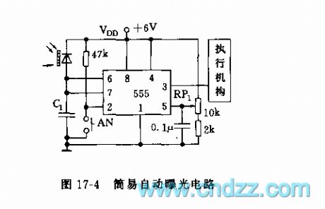
As the figure 17-4 shows, this circuit is composed of a 555 and some resistance, capacitance components. The 555 is the monostable delay time circuit. If you press AN, the 555 sets, pin-3 has the high level voltage, the exposure light or the actuator turns on. The silicon photovoltaic cell suffers the illumination to produce the light current I, and this light current I charges C1, when C1's voltage is more than 2/3VDD, 555 circuit resets, pin-3 has the low level voltage, the exposure light or the actuator has no power to work. The threshold electrical level can be adjusted by RP1, the value is more than 1.4V.
(View)
View full Circuit Diagram | Comments | Reading(552)
555 water form color light control circuit
Published:2011/5/21 9:08:00 Author:TaoXi | Keyword: water form, color light, control circuit
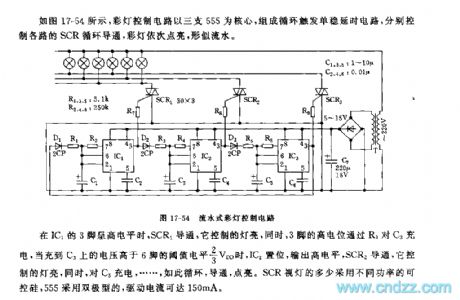
As the figure 17-54 shows, the color light control circuit uses three 555 as the core, and the monostable circuit is composed of the 555, they control the SCR cycle conduction of different channels, so the color light turns on one by one, just like the water.
When the pin-3 of IC1 has the high level voltage, SCR1 conducts, the light turns on. At the same time, pin-3's high level voltage charges C3 through R3, when C3's voltage is higher than pin-6's threshold level 2/3VDD, IC2 sets and outputs the high level voltage, SCR2 conducts, the light turns on, at the same time it charges the C5. 555 is the bipolar type, the driving current is up to 150mA.
(View)
View full Circuit Diagram | Comments | Reading(501)
555 variable delay lighting auto off light circuit
Published:2011/5/21 7:58:00 Author:TaoXi | Keyword: variable, delay, lighting, auto off light
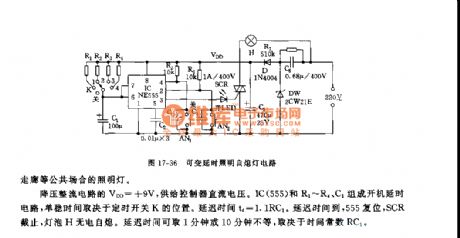
As the figure 17-36 shows, this circuit is composed of the step-down rectifier circuit, the boot timing circuit and the SCR control circuit, and it can be used in wide range of applications such as the floodlight of the staircases and corridors.
The step-down rectifier circuit's VDD=+9V, it supplies the DC current to the controller. The boot delay circuit is composed of the IC (555) and R1 ~ R4, C1, the monostable time depends on the position of the timing switch K. The delay time td=1.1RC1. When the delay time is over, 555 resets, SRC cuts off, the light bulb H automatic turns off. The delay time is between one minute to ten minutes and it depends on the time constant RC1.
(View)
View full Circuit Diagram | Comments | Reading(1271)
Scintillation Caution Light (1)
Published:2011/5/27 6:17:00 Author:Sue | Keyword: Scintillation, Caution Light
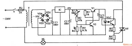
When the circuit begins to work, V1 will output oscillator current. When the current goes through the LED, the LED will be illuminated from time to time. HL is twinkling.
When it is in the daytime, RG has a low resistance value, and the voltage is low too. V2 is disconnected and the circuit doesn't work. HL is not illuminated. When it is in the dark, RG's resistance value becomes larger and the voltage becomes higher. Multivibrator consists of V1 V2 begins to work. The red scintillation caution light HL will begin to twinkle. (View)
View full Circuit Diagram | Comments | Reading(608)
Negative feedback circuit of Pure dc current made by LM3886
Published:2011/6/2 5:49:00 Author:chopper | Keyword: Negative feedback circuit, Pure dc current
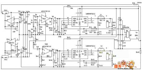
LM3886 is of excellent performance and win its popularity on sound system in recent years.Many power amplifiers use it as the latter stage amplifier or supper bass amplifying circuit directly. It uses LM3886TF as power amplifier which is a new hi-fi stereo amplifier integrated circuit produced by US company NS(a semiconductor company of State) and uses operational amplifier NE5532 or AD827 as leading linear amplifier and tone amplifier.
(View)
View full Circuit Diagram | Comments | Reading(3383)
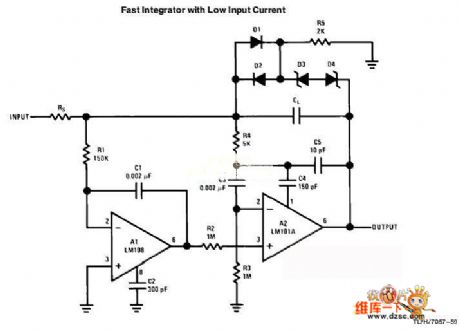
Fast integrator with low input current circuit
Published:2011/6/1 2:08:00 Author:chopper | Keyword: Fast integrator, low input current
View full Circuit Diagram | Comments | Reading(961)
digital isolation circuit
Published:2011/5/30 5:08:00 Author:chopper | Keyword: digital isolation
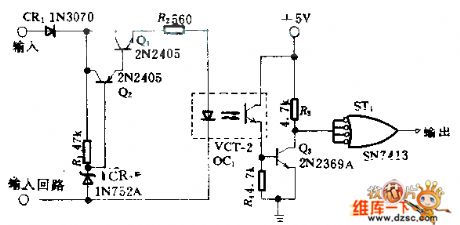
This circuit uses photocoupler to reach a absolute isolation between two digital circuit.The input signal even if it is low to 4V can also change the state of output,and the circuit will not be punctured even though a input peak around +100V.Q1,Q2 form current stabilizer and limit the loop current of the input end through the optoelectronic isolator in 7mA. Zener diode CR2 offers reference voltage and controls the current through R2.Schmitt trigger on the output end eliminates oscillation. (View)
View full Circuit Diagram | Comments | Reading(785)
Temperature centralized controller circuit diagram
Published:2011/6/1 7:09:00 Author:Lucas | Keyword: Temperature, centralized controller
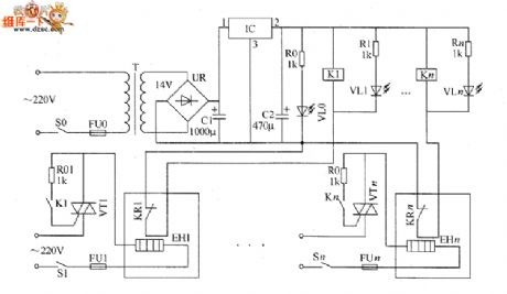
The temperature centralized controller circuit consists of the power supply circuit and temperature control circuit, and the circuit is shown as the chart. The power circuit is composed of the power switch SO, fuse FUO, power transformer T, brigde rectifier UR, filter capacitors C1 and C2, three-terminal regulator integrated circuit IC, current-limiting resistor RO and power indicator LED VLO. Temperature control circuit is composed of the relays K1 ~ Kn, thermal relay sKR1 ~ KRn, resistors R01 ~ R0n, R1 ~ Rn, thyristors VT1 ~ VTn, fuses FU1 ~ FLn, heater case power switches S1 ~ Sn, electric heater(heater case,electric heater), EH1 ~ EHn and work instructor LEDs VL1 ~ VLn. RO ~ Rn and R01 ~ R0n use 1/4W carbon film resistors or metal film resistors.
(View)
View full Circuit Diagram | Comments | Reading(742)
CMOS control signal circuit diagram
Published:2011/6/1 19:50:00 Author:Lucas | Keyword: CMOS , control signal
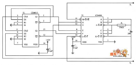
CMOS control circuit is a pulse-width modulation (PWM) circuit, PWM waveform is mainly composed of the CD4001 NOR gate circuit and CD4013 D flip-flop, and the circuit is shown as the chart.
(View)
View full Circuit Diagram | Comments | Reading(1520)
Hazardous area alarm circuit diagram 3
Published:2011/6/2 3:57:00 Author:Lucas | Keyword: Hazardous area , alarm
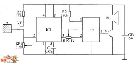
The hazardous area alarm circuit is composed of the induction electrode piece A, JFET VP, time-base integrated circuit ICl, language integrated circuit IC2, audio amplifier tube V and speaker BL, and the circuit is shown as the chart. Adjusting the resistance of RP1 and RP2 can change the sensitivity of the circuit, so if people were less than 0.5m from the induction electrode piece, the alarm will emit sound. If people were 0.5m far away from the induction electrode piece, the alarm does not emit sound. R1 and R2 select 1/4W carbon film resistors. RP1 and RP2 use sealed variable resistors. C uses polyester capacitor or monolithic capacitor. V uses 59013 silicon NPN transistor. VF uses 3DJ6 field effect transistor. BL uses 0.5W, 8Ω electric speaker.
(View)
View full Circuit Diagram | Comments | Reading(963)
Hazardous area alarm circuit diagram 2
Published:2011/6/2 3:49:00 Author:Lucas | Keyword: Hazardous area, alarm
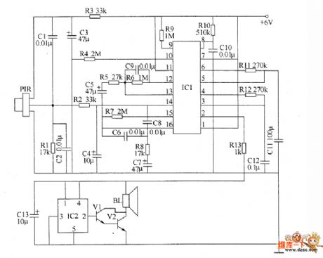
The hazardous area alarm circuit is composed of the pyroelectric infrared sensor (PIR), signal processing circuit and the language remind circuit, and the circuit is shown as the chart. Signal processing circuit is composed of the pyroelectric infrared signal processing integrated circuit IC1 and resistors R4 ~ R12, capacitors C4 ~ C12. The language remind circuit is composed of the speech integrated circuit IC2, transistors V1 and V2, resistor R13, capacitor C13 and speaker BL. R1 ~ R13 use 1/4W carbon film resistors. C1, C2, C4, C6 and C8 ~ C12 use polyester capacitors or monolithic capacitors; C3, C5, CT, C13 select aluminum electrolytic capacitors with the voltage in 10V. V1 selects 59013 NPN silicon transistor; V2 uses 58050 silicon NPN transistor. BL uses 0.25 ~ 0.5W, 8Ω electric speaker.
(View)
View full Circuit Diagram | Comments | Reading(1863)
Motor protector circuit diagarm 3
Published:2011/6/2 3:38:00 Author:Lucas | Keyword: Motor protector
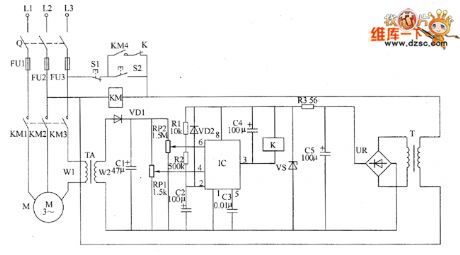
Motor protector circuit is composed of the power circuit, current detection circuit and protection control circuit, and the circuit is shown as the chart. Power supply circuit is composed of the power transformer T, bridge rectifier UR, filter capacitor C5, and the current limiting resistor R3 and regulator diode VS. Current detection circuit is composed of the current transformer TA, diode VD1, capacitor C1 and potentiometers RP1, RP2. Protection control circuit is composed of the time base control circuit IC IC, resistors R1, R2, diode VD2, capacitors C2 ~ C4, AC contactor K and relay KM. S1 is the stop button, S2 is the start button. R1 and R2 select 1/4W carbon film resistors; R3 uses 1W metal film resistor. RP1 uses WHW sealed membrane variable resistor; RP2 uses WSW organic solid variable resistor.
(View)
View full Circuit Diagram | Comments | Reading(906)
Hazardous area alarm circuit diagram 1
Published:2011/6/2 3:44:00 Author:Lucas | Keyword: Hazardous area , alarm
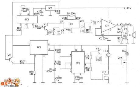
The voltage-stabilizing circuit is composed of three-terminal voltage regulator integrated circuit IC2, resistor R3, zener diode VS and filter capacitors C1, C2. Pyroelectric infrared detecting trigger circuit is composed of the pyroelectric infrared detection module IC1, transistors V1, V2, resistors R1, R2 and potentiometer RP. Electronic switch circuit consists of the electronic switch IC IC5, resistors R9, R10 and capacitor C8. Audio power amplifier consists of the power amplifier integrated circuit IC4, resistors R6 ~ R8, capacitors C4 ~ C7 and speaker BL. Low-frequency oscillator circuit consists of the time-base integrated circuit IC6, resistors R11, R12 and capacitors C9, C10 and other components.
(View)
View full Circuit Diagram | Comments | Reading(765)
Xunda elevator QKS9/10 three-phase AC door-opening circuit
Published:2011/6/2 1:06:00 Author:TaoXi | Keyword: Xunda, elevator, three-phase, AC, door-opening
Xunda elevator QKS9/10 three-phase AC door-opening circuit (View)
View full Circuit Diagram | Comments | Reading(546)
Xunda elevator QKS6/12 three-phase AC door-opening circuit (2)
Published:2011/6/2 1:08:00 Author:TaoXi | Keyword: Xunda, elevator, three-phase, AC, door-opening
Xunda elevator QKS6/12 three-phase AC door-opening circuit (2) (View)
View full Circuit Diagram | Comments | Reading(468)
Xunda elevator QKS6/12 three-phase AC door-opening circuit (1)
Published:2011/6/2 1:08:00 Author:TaoXi | Keyword: Xunda, elevator, three-phase, AC, door-opening
Xunda elevator QKS6/12 three-phase AC door-opening circuit (1) (View)
View full Circuit Diagram | Comments | Reading(516)
Xunda VFP elevator band-type brake circuit
Published:2011/6/2 1:44:00 Author:TaoXi | Keyword: Xunda, elevator, band-type brake
Xunda VFP elevator band-type brake circuit (View)
View full Circuit Diagram | Comments | Reading(496)
Xunda MB-DS elevator band-type brake circuit
Published:2011/6/2 1:39:00 Author:TaoXi | Keyword: Xunda, elevator, band-type brake
Xunda MB-DS elevator band-type brake circuit (View)
View full Circuit Diagram | Comments | Reading(494)
Xunda 300P elevator control power supply circuit
Published:2011/6/2 1:46:00 Author:TaoXi | Keyword: Xunda, elevator, control, power supply
Xunda 300P elevator control power supply circuit (View)
View full Circuit Diagram | Comments | Reading(640)
Xunda VFP elevator outside call button indicator light circuit
Published:2011/6/2 1:45:00 Author:TaoXi | Keyword: Xunda, elevator, outside, call button, indicator light
Xunda VFP elevator outside call button indicator light circuit (View)
View full Circuit Diagram | Comments | Reading(624)
| Pages:255/312 At 20241242243244245246247248249250251252253254255256257258259260Under 20 |
Circuit Categories
power supply circuit
Amplifier Circuit
Basic Circuit
LED and Light Circuit
Sensor Circuit
Signal Processing
Electrical Equipment Circuit
Control Circuit
Remote Control Circuit
A/D-D/A Converter Circuit
Audio Circuit
Measuring and Test Circuit
Communication Circuit
Computer-Related Circuit
555 Circuit
Automotive Circuit
Repairing Circuit