
Control Circuit
Index 249
555 hand-wave stop noising electric clock circuit
Published:2011/6/7 3:35:00 Author:TaoXi | Keyword: 555, hand-wave, stop noising, electric clock
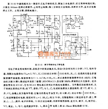
When the electric clock goes to the alarm moment, the contact point K1 of the original movement closes (the closing time is about 2 minutes), VT5 conducts, the additional circuit gets the power. The astable multivibrator which is composed of the left part (1/2 556) of the IC1(556) and the R9, R10, C7 starts oscillation, the oscillation frequency f=1.44/(R9+2R10)C7, the parameters of the figure has the oscillation frequency of 38kHz, it outputs the square wave to drive the infrared emitting diode LED(HG411).
When the hand is near the probe, the infrared ray which is reflected by the hand is received by the VT1, then this infrared ray is selected by the frequency-selecting amplifier which is composed of the VT2 and L1, C3 to rise the VT3's Vc.
(View)
View full Circuit Diagram | Comments | Reading(644)
888 safety box and refrigerator door-opening over-time sound alarm circuit
Published:2011/6/7 3:53:00 Author:TaoXi | Keyword: 888, safety box, refrigerator, door-opening, over-time, sound alarm
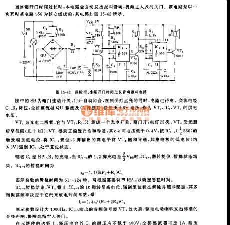
The SB in the figure is the refrigerator door linkage switch, when the door opens, the SB automatically shuts off, when the light turns on, the circuit gets power. The alternating current is reduced by C1 and R1, then it is rectified by the full bridge rectifier QU and is filtered by C2 to output the +9V voltage.
The VT4 is the photoelectric diode, the photoelectric switch is composed of the VT1, R3, R4 and the VT4. When the refrigerator door is opening, the light H turns on. VT4 has the low resistance because of the illumination (tens of thousands of ohms), VT1 gets the positive bias to conduct, the voltage between c and e is lower than 0.4V to make the IC1-n(1/2 556)'s trigger port has low electric potential, if you set the IC1-n, the pin-5 outputs the high electrical level to conduct the VT2.
(View)
View full Circuit Diagram | Comments | Reading(592)
555 time control password electronic doorbell circuit
Published:2011/6/7 5:16:00 Author:TaoXi | Keyword: 555, time control, password, electronic doorbell
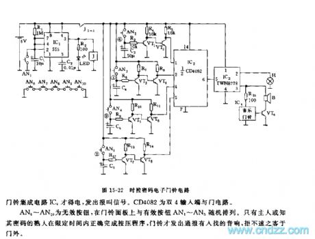
As the figure 15-22 shows, the doorbell is composed of the monostable timing circuit, the password switch, the NAND gate circuit and the sound circuit.etc. In the limited time, the circuit uses the program to press the password switch, the doorbell circuit sends out the alarm sound. If it exceeds the specified time or the password is wrong, there is no sound signal.
The timing switch circuit is composed of the IC1(555) and R1, C1, AN1, the timing time td=1.1R1C1, the figure parameter is 11 seconds. If you press AN1, the 555 will set, J and J1-1 contact point close to connect the power supply voltage of VT1~VT8,IC2,IC3.etc, the turn-on time is 11 seconds. The four groups of electronic switch is composed of the AN2~AN5,VT1~VT8.etc, the AN6~AN10 are the Invalid buttons.
(View)
View full Circuit Diagram | Comments | Reading(1431)
555 time limiting lock alarm device circuit
Published:2011/6/7 6:43:00 Author:TaoXi | Keyword: 555, time limiting, lock, alarm device
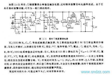
As the figure 15-21 shows, the door lock alarm device is composed of the monostable trigger circuit, the timer and the alarm sound circuit.etc. It has the function of time limit, so it can be used as the subsidiary part of the door lock.
The touch trigger is composed of the IC1(555) and R1, C1, C2.etc, the sequin M which is connected with pin-2 connects with the metal part of the door lock, when someone uses opens the lock, the human body sensor signal will set the IC1, Vt1 conducts and VT2 cuts off. C4 is charged through R4. The monostable timing circuit is composed of the C4, R4 and IC2(555), when C4 is charged to the 1/3VDD=1.5V, IC2 sets and VT3, VT4 conduct to open the IC3's power supply. IC3 uses the four stereo analog manifold KD9561.
(View)
View full Circuit Diagram | Comments | Reading(641)
555 fish tank water temperature automatic heating control circuit
Published:2011/6/7 8:10:00 Author:TaoXi | Keyword: 555, fish tank, water temperature, automatic, heating control
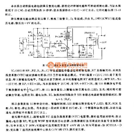
This fish tank water temperature automatic heating control circuit is composed of the step-down rectifier circuit, the humidity control timing circuit and the silicon-controlled rectifier control circuit. When the fish tank water temperature is lower than 25℃, the circuit automaticly heats for 10 seconds to keep the water temperature in the range of +25℃ to +30℃. The circuit is as shown in figure 15-49.
The step-down rectifier circuit is composed of the step-down transformer T, the rectifier diodes D1 and D2, and the voltage-stabilizing circuit which is composed of the R4 and DW outputs the +9V voltage.
The temperature control monostable timing circuit is composed of the IC1(555) and RP1, RT, R1, R2, C1. RT is the temperature sensitive component, it uses the negative temperature coefficient (NTC) glass sealing thermistor, the 555 works in the monostable mode.
(View)
View full Circuit Diagram | Comments | Reading(1250)
Mine spray dedusting controller circuit diagram
Published:2011/6/10 6:26:00 Author:Lucas | Keyword: Mine spray, dedusting, controller
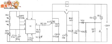
The mine spray dedusting controller circuit consists of +6 V power supply circuit, light control circuit, LED indication circuit and the solenoid valve control circuit, and the circuit is shown as the chart. +6 V power supply circuit consists of the illuminating lamps EL1, EL2, resistors R4, R5, switch S, diodes VD1, VD2, filter capacitors C5, C6, Zener diode V and transistor VS. Light control circuit consists of the photosensitive resistors RGI, RG2, potentiometers RP1, RP2, capacitors C1 ~ C3 and the time-base integrated circuit IC. Solenoid valve control circuit is composed of the internal circuit of IC, resistors R2, R3, thyristor VT, capacitor C4 and electromagnetic valve YV. LED indicating circuit is composed of the resistor R1 and LED VL. R1 and R4 select 1/4W metal film resistors; R2 uses 1W film resistor.
(View)
View full Circuit Diagram | Comments | Reading(1152)
Mine locomotive remote controller circuit diagarm
Published:2011/6/10 6:13:00 Author:Lucas | Keyword: Mine locomotive , remote controller
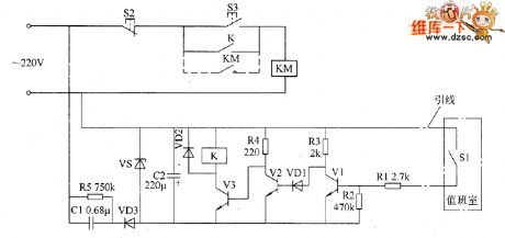
The mine locomotive remote controller circuit consists of transistors V1 ~ V3, capacitors C1 and C2, resistors R1 ~ R5, diodess VD1 and VD2, Zener diode VS and the control switch S1, and the circuit is shown as the chart. Stop button S2, start button S3, AC contactor KM and the normally open contact of K form the main control circuit of Stepless rope motor M (it is not shown in the circuit). VS, C1, C2, R5, and VD3 form the regulated power supply circuit, and the control switch S1 is installed in the duty room, then the one end is connected to the ground, and the other end is connected to R1 by wire. AC 220V voltage bucked by C1, rectified by VD3, filtered by C2 and stabilized by vs to provide 9V DC voltage for relay control circuit. R1 ~ R5 use 1/4W carbon film resistors or metal film resistors.
(View)
View full Circuit Diagram | Comments | Reading(717)
The sound and light alarm circuit diagram 1 for industrial instrumentation
Published:2011/6/9 4:40:00 Author:Lucas | Keyword: sound , light, alarm, industrial instrumentation
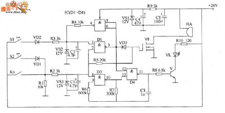
The sound and light alarm circuit for industrial instrumentation is composed of the detection control circuit, bistable trigger, LED flash circuit, sound alarm circuit and +12 V voltage regulator circuit, and the circuit is shown as the chart. Detection control circuit is composed of controlled contact of industrial instrument (controlled electric contact) Kx, resistors R1, R2, zener diode VS3 and capacitors C1. LED flash circuit consists of the D3, D4 which are inside of NAND gate integrated circuit IC (D1 ~ D4), resistors R6 ~ R8, R10, capacitor C3, transistor V and LED VL. Sound the alarm circuit is composed of resistor R5, field-effect transistor VF and alarm HA. R1 ~ R8 select l/4W metal film resistors.
(View)
View full Circuit Diagram | Comments | Reading(1257)
Scintillation Caution Light (4)
Published:2011/6/3 5:35:00 Author:Sue | Keyword: Scintillation, Caution, Light
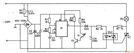
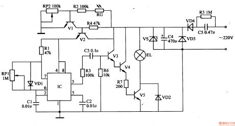
When the oscillator begins to work, IC's 3 pin outputs 1 Hz low frequency square form wave signals. When the signal is positive, VD5 is connected and VLC's LED is illuminated. VT is connected and HL is illuminated.
When the signal is negative, VD5 is disconnected. VLC's LED has a weaker light and HL's light becomes weaker.
Before HL goes out, another positive signal comes and it is illuminated again.
In the daytime, V2 is connected and IC's 4 pin has a low level. VLC and VT are disconnected. HL is not illuminated.
At night, VI has a high resistance value and IC begins to work. (View)
View full Circuit Diagram | Comments | Reading(604)
Scintillation Caution Light (3)
Published:2011/6/3 5:30:00 Author:Sue | Keyword: Scintillation, Caution, Light
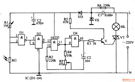
In the daytime, RG has a low resistance value. IC's 1 pin and 2 pin have low level and 3 pin has high level. The low frequency oscillator doesn't work. IC's 10 pin outputs oscillator signals and V is disconnected. VT is disconnected and HL is not illuminated.
When there is no light, RG has a high resistance value. IC's 1 pin and 2 pin have high level. 3 pin has low level and 4 pin has high level. The oscillator begins to work. IC's 10 pin outputs low frequency oscillator signals. V and VT are connected and HL is illuminated. (View)
View full Circuit Diagram | Comments | Reading(608)
Scintillation Caution Light (2)
Published:2011/6/3 5:24:00 Author:Sue | Keyword: Scintillation, Caution, Light
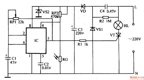
In the daytime, resistance RG has a low resistance value because of the light. IC's 4 pin has a voltage lower than 0.4V. The multivibrator doesn't work. 3 pin outputs low level, and VT is disconnected. HL is not illuminated.
When there is no light, RG has a high resistance value. IC's 4 pin has a voltage higher than 0.4V. The multivibrator begins to work. IC's 3 pin outputs high level and low level with a certain frequency. VT is connected from time to time. HL begins to twinkle. (View)
View full Circuit Diagram | Comments | Reading(508)
Light-Operated Night Lamp (3)
Published:2011/5/27 6:39:00 Author:Sue | Keyword: Light-Operated, Night Lamp
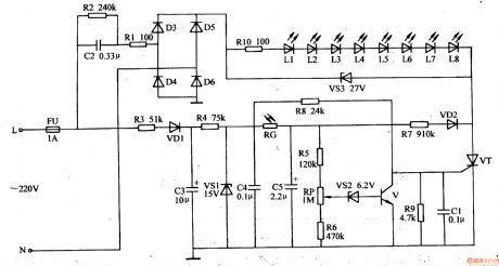
The 220V voltage will provide LED circuit with working voltage after reduction, rectification. Another circuit will provide light-operated electronic switch circuit with 15V ac voltage after reduction, rectification, filtration and stablization.
In the daytime, RG's resistance value is small because of the light. VS2 is connected and V is connected. VT is disconnected and VL1-VL8 are not illuminated.
At night, RG's resistance value becomes large. C5's voltage becomes lower. VS2 and V are disconnected. R8,R9 will provide VT with voltage. VT is connected and VL1-VL8 are illuminated. (View)
View full Circuit Diagram | Comments | Reading(1769)
Light-Operated Night Lamp (2)
Published:2011/5/27 6:34:00 Author:Sue | Keyword: Light-Operated, Night Lamp
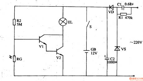
The power circuit consists of C1,R1,VS,VD,C2,S and GB.
The light-operated circuit consists of R2,RG,V1 and V2.
The alternating current voltage of 220V can provide EL and the circuit with 12V voltage after reduction, stablization, rectification and filtration. It can also charge GB by S.
In the daytime, RG will have a small resistance value because of the light, and V1,V2 are disconnected. EL is not illuminated. At night, RG has a large resistance value. Its voltage is higher than 1.4V and V1 V2 are connected. EL is illuminated. (View)
View full Circuit Diagram | Comments | Reading(588)
Light-Operated Night Lamp (1)
Published:2011/5/27 6:41:00 Author:Sue | Keyword: Light-Operated, Night Lamp
When the multivibrator begins to work, IC's 3 pin outputs pulse signals, which will illuminate EL after amplification.
When it is in the daytime or there is light, RG's resistance value will become small. V1 will be connected and V2 will be disconnected. IC stops working because of lack of power.EL is not illuminated.
When it is dark, RG's resistance value become larger. V1 is disconnected and V2 is connected. The multivibrator and the output circuit will begin to work and EL is illuminated. (View)
View full Circuit Diagram | Comments | Reading(615)
Illuminations Controller (1)
Published:2011/5/29 20:31:00 Author:Sue | Keyword: Illuminations, Controller
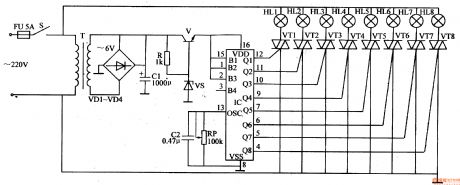
When S1 is connected, 220v voltage will generate +5V voltage after reduction, rectification,filtrition, which will be sent to IC,V0-V7. When IC begins to work, Y0-Y7 will output high level pulse, and V0-V7 will be connected. VT0-VT7 will be connected. 8 circuit illuminations will be turned on. When any transistor of V0-V7 is connected, its LED will be illuminated as monitor.
IC's OSCR terminal is connected with RP. When RP's resistance value is changed, the twinkle frequency of the illuminations will be changed. (View)
View full Circuit Diagram | Comments | Reading(456)
Illuminations Controller (2)
Published:2011/5/29 20:36:00 Author:Sue | Keyword: Illuminations, Controller
When S is connected, alternating current voltageof 220v will provide IC with 5v direct current voltage after reduction, rectification, filtrition and stablization.
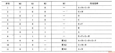
When IC begins to work, its output terminal will output high level according to the set illuminating way. The transistors will control the illuminations.
The circuit connects IC's 1 pin 2 pin and 15 pin together, and makes the illuminating way vary from A to F automatically. (View)
View full Circuit Diagram | Comments | Reading(530)
555 ultrasound remote control voice doorbell circuit
Published:2011/5/30 8:37:00 Author:TaoXi | Keyword: 555, ultrasound, remote control, voice doorbell
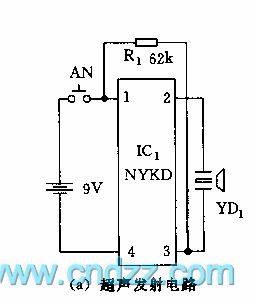
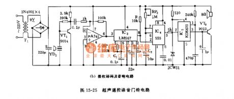
As the figure 15-25 shows, the doorbell is composed of the ultrasound launch circuit and the receiving decoding and audio circuit. This circuit can remote control the voice circuit at the distance of 10 meters.
The launcher uses the special ultrasound launch integrated circuit NYKD to drive the piezoelectric ceramic ultrasound emission sensor YD1 to send out the 40kHz ultrasonic wave. If you press AN, this circuit sends out a string of modulation ultrasonic pulse wave.
The IC3 uses the audio decoder LM567 which has the phase-locked loop (PLL). When there is no signal, the output port pin-8 has the high electrical level because of the R=10kΩ bias, when there is the input signal, it outputs the negative hopping pulse to trigger the IC4 monostable circuit. The center frequency f0 of the IC3 should be set at the 40kHz frequency emission.
(View)
View full Circuit Diagram | Comments | Reading(1122)
555 alarm, doorbell and lighting controller circuit
Published:2011/5/30 10:11:00 Author:TaoXi | Keyword: 555, alarm, doorbell, lighting, controller
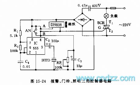
As the figure 15-24 shows, the controller circuit is composed of the switch type Hall integrated circuit DN838 and the astable multivibrator (composed of the 555), this circuit can be used in wide range of applications such as the automatic door opening, automatic delay alarm, automatically turns off the lights and also it can be used as the doorbell.
The astable multivibrator is composed of the IC(555) and R1,R2,C1, the oscillation frequency f=1.44/(R1+2R2)C1, it is about 1000Hz. The reset switch and the SCR trigger switch are composed of the DN838 and the small magnets. When the DN838 loses the magnetism, poins A and B conduct, SCR is trigger conduction, the light turns on, the 555 starts working, the piezoelectric ceramic HTD sends out the alarm. When you close the door, the DN838 receives the magnetism, points A and B cut off, the SCR cuts off too, the light turns off.
(View)
View full Circuit Diagram | Comments | Reading(2223)
555 household appliances protector circuit
Published:2011/6/2 18:59:00 Author:TaoXi | Keyword: 555, household appliances, protector
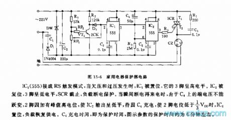
As the figure 15-6 shows, the household appliances protector is composed of the step-down rectifier circuit, the under-voltage over-voltage sampling circuit and the monostable delay circuit.etc.
The IC1(555) is in the RS trigger mode, when it is under-voltage or over-voltage, IC1 is set, so pin-3 has the low electrical level, SCR cuts off, the load is out of power. When the power is coming, the terminal voltage of C4 can not be abrupt-change, and pin-2 has the high potential peak to make the IC2 to output the low electrical level, when the C4 is charged until pin-2's electrical level is lower than 1/3VDD, IC2 sets, the load restores the power supply.
(View)
View full Circuit Diagram | Comments | Reading(751)
555 home appliance automatic opening and closing timing circuit
Published:2011/6/6 8:31:00 Author:TaoXi | Keyword: 555, home appliance, automatic, opening, closing, timing
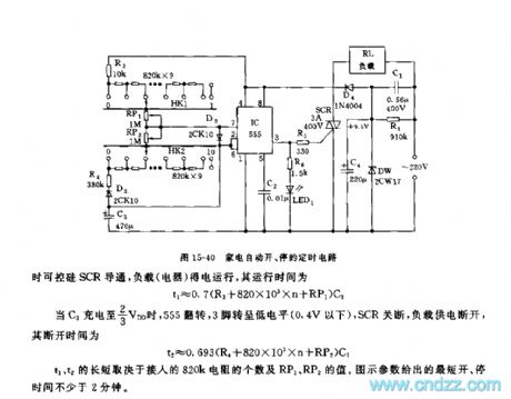
The multivibrator is composed of the 555 and R3,R4,C3. the HK1 and HK2 are the 1X11 single-blade rotary switches, the 820kX9 and RP1, RP2 are connected with them, the 820kX9 and RP1, RP2 can be used in the coarse adjustment and fine adjustment of the oscillation period and the duty ratio. When the 555 outputs the high electrical level, LED1 turns on, at the same time the SCR conducts and the load gets power to work.
When the C3 is charged to 2/3VDD, the 555 everts, pin-3 has the low electrical level (lower than 0.4V), the SCR turns off and the load has no power.
The length of t1, t2 depends on the number of the 820k resistances and the values of RP1 and RP2. The parameters of the figure show the shortest switch time of not less than 2 minutes.
(View)
View full Circuit Diagram | Comments | Reading(690)
| Pages:249/312 At 20241242243244245246247248249250251252253254255256257258259260Under 20 |
Circuit Categories
power supply circuit
Amplifier Circuit
Basic Circuit
LED and Light Circuit
Sensor Circuit
Signal Processing
Electrical Equipment Circuit
Control Circuit
Remote Control Circuit
A/D-D/A Converter Circuit
Audio Circuit
Measuring and Test Circuit
Communication Circuit
Computer-Related Circuit
555 Circuit
Automotive Circuit
Repairing Circuit