
Control Circuit
Index 246
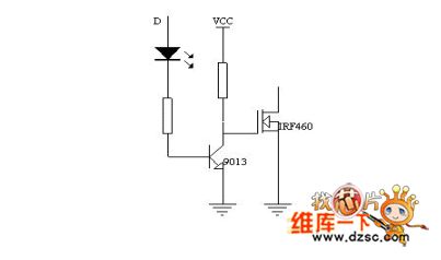
The FET switch pipe gate source voltage amplifier circuit
Published:2011/6/20 10:43:00 Author:Seven | Keyword: FET, switch pipe, amplifier circuit
View full Circuit Diagram | Comments | Reading(650)
The frequency shift key control modem circuit of XR-2207
Published:2011/6/19 7:49:00 Author:Seven | Keyword: frequency shift, key control modem
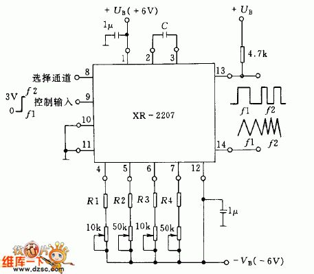
XR-2207 is a voltage control oscillating (VCO) function generator circuit, the modem circuit shown in the figure can generate rectangle wave and triangular wave (but it can't generate the sine wave).
(View)
View full Circuit Diagram | Comments | Reading(1810)
The FT2275 (general) infrared remote control decoding circuit
Published:2011/6/19 7:52:00 Author:Seven | Keyword: infrared remote control, decoding circuit
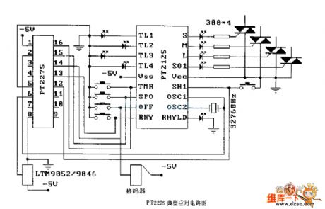
Figure: The FT2275 (general) infrared remote control decoding circuit (View)
View full Circuit Diagram | Comments | Reading(615)
The trigger circuit with functions of counting, setting and reset
Published:2011/6/19 7:55:00 Author:Seven | Keyword: trigger circuit, reset
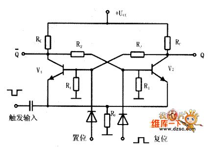
The trigger circuit with functions of counting, setting and reset
(View)
View full Circuit Diagram | Comments | Reading(567)
The SAA3009/SAA3049 infrared remote control decoding circuit
Published:2011/6/19 8:09:00 Author:Seven | Keyword: infrared, remote control, decoding circuit

The SAA3009/SAA3049 typical application circuit (View)
View full Circuit Diagram | Comments | Reading(1697)
The MC3367 (communication equipment) FM receiver circuit
Published:2011/6/19 1:16:00 Author:Seven | Keyword: communication equipment, FM receiver
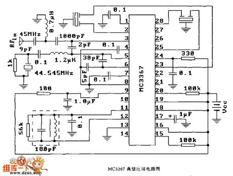
Figure: The MC3367 (communication equipment) FM receiver circuit (View)
View full Circuit Diagram | Comments | Reading(984)
Inductive anti-theft alarm circuit diagram
Published:2011/6/14 5:06:00 Author:Lucas | Keyword: Inductive, anti-theft alarm
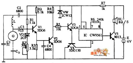
The circuit is shown as the chart. The voltage on R3 is higher to stop the multiple valve composed of V4 and V2 and conduct V2, and it cuts off the four tones analog integrated circuit, and the speaker does not sound. When someone closes to the sensor, the value of C0 increases and the high-frequency differential pressure decreases. The voltage sent to the base of V1 by C3 can not maintain the oscillation of V1 and V1 stops vibration immediately. At this point the voltage on R3 becomes smaller, and V2 stops, then V3, V4 conduct and the pin ② of IC gets power and works.Pin ③ emits siren signal which is amplified by the V5 and output from the loudspeaker, and it will emit warning sound.
(View)
View full Circuit Diagram | Comments | Reading(1238)
Irrigation motor automatic protector circuit diagram 2
Published:2011/6/14 4:19:00 Author:Lucas | Keyword: Irrigation motor, automatic protector
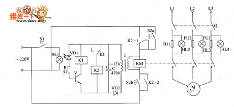
The irrigation motor automatic protector circuit is composed of the starter control circuit, phase failure protection circuit and test circuit, and the circuit is shown as the figure. Starting circuit is composed of the starter button S2 (S2a, S2b), AC contactor KM and relay K2 and so on. Phase failure protection circuit is composed of the indicators HL2 ~ HL4, photosensitive diode VD1, resistor R, transistor V, capacitor C, diode VD2, power transformer T and the relay K1. Test circuit consists of the test button Sl, light sensitive diode VD1 and indicator light HL1. R selects 1/4W metal film resistor or carbon film resistor. C uses the aluminium electrolytic capacitor with the voltage in 25V.
(View)
View full Circuit Diagram | Comments | Reading(1851)
Intermittent power controller circuit diagram 5
Published:2011/6/16 4:01:00 Author:Lucas | Keyword: Intermittent , power controller
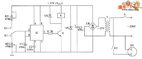
The intermittent power control circuit is composed of the power supply circuit and timing control circuit, and the circuit is shown as the Figure. Power supply circuit is composed of the power switch s, power transformer T, bridge rectifier UR, filter capacitor C3 and Zener VS . Timing control circuit consists of the time-base integrated circuit IC, transistor V, Relay K, potentiometers RP1, RP2, capacitor C1, C2, resistor R and diode VD. R uses the 1/4W carbon film resistor. BP1 and RP2 use organic, solid potentiometers. C1 and C3 select the aluminum electrolytic capacitors with the voltage in 25V.
(View)
View full Circuit Diagram | Comments | Reading(573)
Agricultural irrigation controller circuit diagram 1
Published:2011/6/16 4:11:00 Author:Lucas | Keyword: Agricultural, irrigation controller
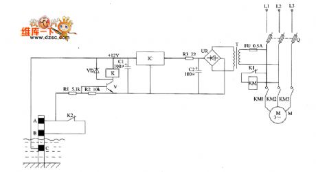
The agricultural irrigation controller circuit is composed of the power supply circuit and the water level detection control circuit, and the circuit is shown as the Figure. Power supply circuit is composed of the fuse FU, power transformer T, bridge rectifier UR, filter capacitors C1, C2, current limiting resistor R3 and two terminal integrated voltage regulator IC. Water level detection control circuits is composed of the high water level electrode A, low water level electrode B, main electrode C, resistors RI, R2, transistor V, Relay K, diode VD, AC contactor KM and other components. R1 and R2 use 1/4W carbon film resistors or metal film resistors.
(View)
View full Circuit Diagram | Comments | Reading(1075)
Automatic sprinkler controller circuit diagram 5
Published:2011/6/16 5:24:00 Author:Lucas | Keyword: Automatic , sprinkler controller
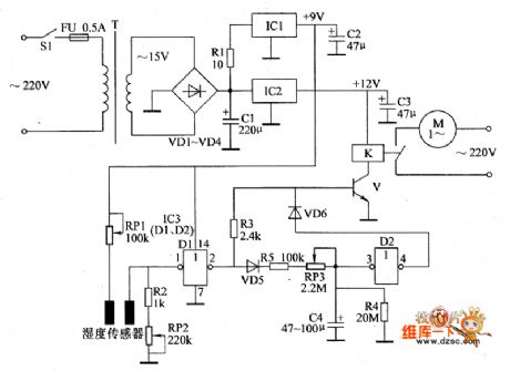
The automatic sprinkler controller circuit is composed of the power supply circuit and humidity measurement and control circuit, and the circuit is shown as the Figure. Power supply circuit is composed of the power transformer T, rectifier diodes VD1 ~ VD4, filter capacitors C1 ~ C3 and three-terminal integrated regulators ICl, IC2 and so on. Humidity measurement and control circuits is composed of the humidity detector, NOT gate integrated circuit IC3 (Dl, D2), transistor V, Relay K and the external components. R1 uses l/2W carbon film resistor: R2 ~ R5 select l/4W carbon film resistors. RP1 ~ RP3 use small synthetic carbon film potentiator.
(View)
View full Circuit Diagram | Comments | Reading(1621)
Automatic sprinkler controller circuit diagram 4
Published:2011/6/16 5:13:00 Author:Lucas | Keyword: Automatic , sprinkler controller
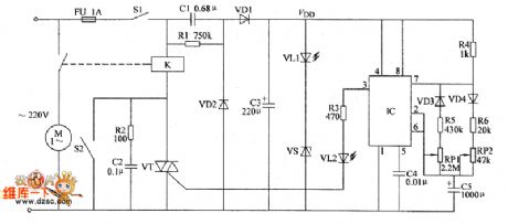
The automatic sprinkler controller circuit is composed of the power supply circuit and timing control circuit, and the circuit is shown as the Figure. Power supply circuit is composed of the fuse FU, power switch S1, step-down capacitor C1, resistor RI, rectifier diodes VD1, VD2, filter capacitor C3, power indicator LED VL1 and Zener vs. The timing control circuit is composed of the time-base integrated circuit IC, timing capacitor C5, Triac VT, relay K, manual / automatic switch S2 and the related external components. R1 ~ R6 select I/4W carbon film resistors or metal film resistors.
(View)
View full Circuit Diagram | Comments | Reading(2124)
Automatic sprinkler controller circuit diagram 3
Published:2011/6/16 5:08:00 Author:Lucas | Keyword: Automatic , sprinkler controller
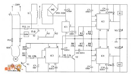
The automatic sprinkler controller circuit is composed of the +12 V power supply circuit, light control circuit and irrigation control circuit, and the circuit is shown as the Figure. +12 V power supply circuit is composed of the knife switch Q, fuse FU2, power switch S1, power transformer T, rectifier diodes VD1 ~ VD4, filter capacitors C1, C2, and three-terminal voltage regulator integrated circuit IC1. Light control circuit is composed of the phototransistor VI, potentiometer RP, resistors R3 ~ R6, capacitors C5, C6, time-base integrated circuit IC3, transistor V2.RI ~ R8 select 1/4W metal film resistors or carbon film resistors.
(View)
View full Circuit Diagram | Comments | Reading(3337)
Automatic sprinkler controller circuit diagram 1
Published:2011/6/16 4:59:00 Author:Lucas | Keyword: Automatic , sprinkler controller
The automatic sprinkler controller circuit is composed of the clock timing controller, monostable flip-flop, bistable flip flop, electronic switch, self-excited multivibrator, counter, solenoid valve control circuit and power supply circuit, and the circuit is shown as the Figure. Power supply circuit is composed of the fuse FU, power switch SO, power transformer T, bridge rectifier UR and filter capacitors C11, C12. Self-excited multivibrator is composed of the time-base IC ICS and the external components, and it is used to generate the count pulse. R1 ~ R26 choose l/4W or 1/8W carbon film resistors.
(View)
View full Circuit Diagram | Comments | Reading(3248)
555 TV starting up timer circuit
Published:2011/6/15 3:34:00 Author:TaoXi | Keyword: 555, TV, starting up, timer circuit
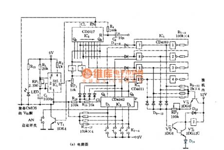
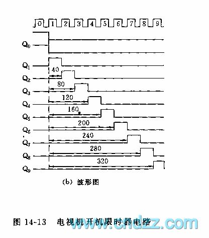
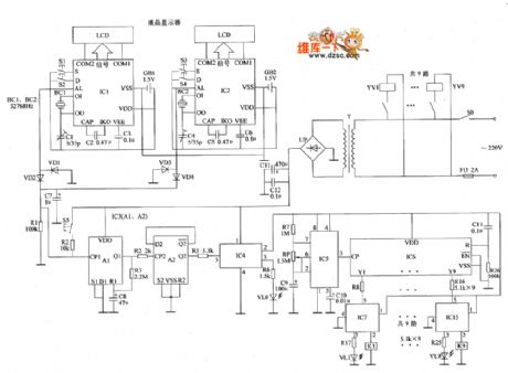
As the figure 14-13 shows, the timer is composed of the benchmark pulse generator, the reservation time limit interlock switch, the counter and the driving circuit. And this device can be used to control the children watching TV time. The time limit has five levels: the limit time of K1 is 40 minutes, the locking time is 280 minutes; the limit time of K2 is 80minutes, the locking time is 240 minutes; the limit time of K3 is 160 minutes, the locking time is 160 minutes; the limit time of K4 is 280 minutes, the locking time is 40 minutes; if you do not press K1~K4, the limit time is 320 minutes.
The astable oscillator is composed of the IC1 (555) and R1, RP1, C1, the oscillation period T=0.693(R1+RP1)C1, the T of the figure parameter is about 40 minutes. The output of it can be used as the count pulse of the counting circuit IC2.
(View)
View full Circuit Diagram | Comments | Reading(1157)
555 automatic radio controller circuit
Published:2011/6/14 4:05:00 Author:TaoXi | Keyword: automatic, radio controller
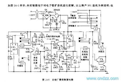
As the figure 14-5 shows, this controller can be used to control the electronic valve audio power amplifier.
When the clock control system connected to the trigger switch S, J1 closes, the power turns on. The boot delay circuit is composed of the IC2 and R2, C3, the delay time td1=1.1R2C3, it is about 2-5 minutes, then the J2 closes to connect the high voltage. The ten minutes delay circuit is composed of the IC2 and C8, R5, if there is no monitor signal in ten minutes, the pin-3 will output the high electrical level to supply power to the IC3, and IC3 outputs the high electrical level to close J3, the high voltage turns off. The monostable delay circuit is composed of the IC3 and C9, RP3, R8, the delay time td2=1.1(R8+RP3)C9, it is about 10 seconds.
(View)
View full Circuit Diagram | Comments | Reading(611)
555 synchronization/quasi-synchronization video-audio switching circuit
Published:2011/6/14 6:19:00 Author:TaoXi | Keyword: 555, synchronization, quasi-synchronization, video-audio, switching
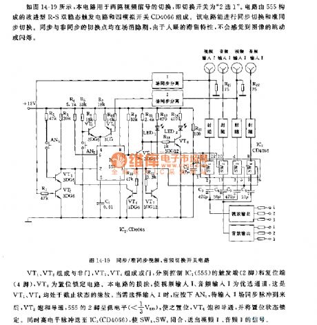
As the figure 14-19 shows, this circuit is composed of the improved R-S bistable trigger circuit (composed of the 555) and the four-analog switch CD4066. This circuit has the function of synchronous switching and quasi-synchronous switching.
The NAND gate is composed of the VT1 and VT2, the OR gate is composed of the VT3 and VT4, they control the IC1(555)'s trigger port (pin-2) and the reset port (pin-4) respectively, VT6 is the set lock circuit. The connection method of this circuit makes the video input I and the audio input I to be the priority channel, that is why the VT1 and VT4 are in the cut-off state. When you need to input I, you should press AN1, the VT2 conducts, the pin-2 of 555 has the low electrical level to lock the set state.
(View)
View full Circuit Diagram | Comments | Reading(757)
555 radio wireless remote control switch additional device circuit
Published:2011/6/14 6:57:00 Author:TaoXi | Keyword: 555, radio, wireless, remote control, switch, additional device
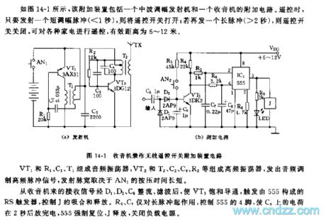
As the figure 14-1 shows, this additional device has a medium-wave amplitude modulation transmitter and a tape recorder additional circuit. When you are remote controlling, this device will launch a short amplitude modulation pulse (<1 second), so the remote control switch turns on; if it launches a long pulse (>2 second), the remote control switch turns on to remote control all sorts of home appliances, the effective distance is 6-12 meters.
The audio oscillator is composed of the VT1 and R1,C1,T1, the high-frequency oscillator is composed of the VT2 and T2, C2, C4, R2 to send out the audio modulation high frequency pulse signal, the pulse width depends on the press-time of AN1.
(View)
View full Circuit Diagram | Comments | Reading(2004)
The outline size diagram of the infrared photoelectric switch
Published:2011/6/11 22:03:00 Author:qqtang | Keyword: outline size, infrared photoelectric switch
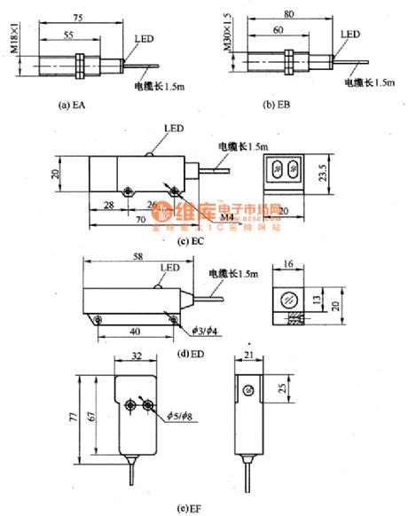
figure: The outline size of the infrared photoelectric switch (View)
View full Circuit Diagram | Comments | Reading(582)
Multi-function telephone control switch circuit
Published:2011/6/12 22:28:00 Author:Christina | Keyword: Multi-function, telephone, control, switch
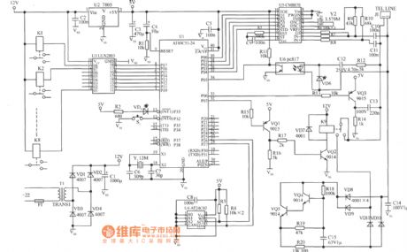
The function of this machine is as follow:
(1)Remote control, local control: the operator can call the telephone which is in parallel with this control through the external, when the number of phone rings is equal to the value of the controller setting, the controller will automatically simulate the off-hook and send out the long beep of Di to remind the operator to input the password.
(2)Off-electrical memory protection
(3)Query function: you can query the opening and closing state of the switch
(4)Automatically hangs up
Components selection: the audions VQ4 and VQ5 can use the 9014. The VD5 and VD6 can use the 5mm red light-emitting diode. The resistance of R20 is 100Ω, the resistance of R19 is 47Ω, the resistance of R18 is 100Ω. The other components is as shown in the figure. (View)
View full Circuit Diagram | Comments | Reading(1498)
| Pages:246/312 At 20241242243244245246247248249250251252253254255256257258259260Under 20 |
Circuit Categories
power supply circuit
Amplifier Circuit
Basic Circuit
LED and Light Circuit
Sensor Circuit
Signal Processing
Electrical Equipment Circuit
Control Circuit
Remote Control Circuit
A/D-D/A Converter Circuit
Audio Circuit
Measuring and Test Circuit
Communication Circuit
Computer-Related Circuit
555 Circuit
Automotive Circuit
Repairing Circuit