
Index 80
PROPORTIONAL_TEMPERATURE_CONTROLLER
Published:2009/6/24 4:01:00 Author:May


Most temperature-controller circuits use upper and lower trip points to control a heater element, with the heater power full on and full off. Usually, this results in a temperature hysteresis of several degrees. This relatively large temperature hysteresis effect might cause modulation in the output of the circuit that's being controlled.
A proportional temperature controller eliminates this problem by continuously providing the power needed to maintain the oven at the desired temperature-within 1℃. From a cold start, maximum power is applied until the temperature is within 2℃ of the set point.
The circuit's mechanical construction is important. The five heater resistors (R12 through R16), the temperature-sensor IC (U1), and the circuit being controlled are mounted with thermal epoxy to a small piece of aluminum. This provides excellent heat transfer between the components. The heater resistors must be selected to raise the temperature from ambient to the set point within an acceptable warm-up time.
U1 is Analog Devices' TMP-01 temperature- controller IC. The voltage proportional to absolute temperature (VPTAT) has a temperature coefficient of exactly 5 mV/℃. The set point is determined by the R1/R2 ratio. U2 is a Linear Technology LT1014 quad precision op amp. U2C is an oscillator with a 50% duty cycle that supplies a triangle wave between 1/3 and 2/3 of the supply voltage at U2-2
U2B compares the amplified VPTAT to the triangle wave, which drives Q1 at a duty cycle of 100% or less. Because the triangle wave's peak-to-peak amplitude is 2.7 V, and VPTAT is amplified by a factor of 300, a temperature change of approximately 2 mV moves the duty cycle from 100% to 0%. (View)
View full Circuit Diagram | Comments | Reading(0)
PHONE_HELPER
Published:2009/6/24 3:44:00 Author:May
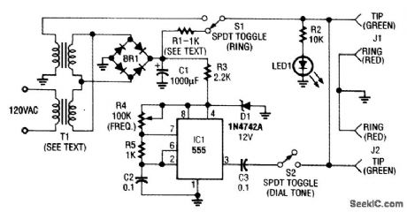
This phone-line simulator uses a 60-Hz transformer instead of a ring generator. The dial tone is provided by an NE555 astable oscillator. (View)
View full Circuit Diagram | Comments | Reading(0)
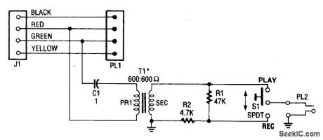
TELEPHONE_RECORDING_CIRCUIT
Published:2009/6/24 3:42:00 Author:May
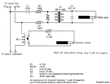
This device will automatically record telephone calls. An ordinary cassette recorder can be hooked to it. (View)
View full Circuit Diagram | Comments | Reading(1183)
UNIVERSAL_TELEPHONE_HOLD_CIRCUIT
Published:2009/6/24 3:41:00 Author:May
The telephone line is connected to the hold components through bridge rectifier BR1 so that the input is not polarity sensitive. If you have touch-tone telephone service, you can now put a call on hold from any phone in your house by plugging this simple device into any telephone jack. The uni-versal hold circuit works with any phone that has a key pad with a # key. To put a call on hold, press the # key and hang the phone up. A timer extends the #-key function while you hang up phones that have a keypad built into the handset. (View)
View full Circuit Diagram | Comments | Reading(1207)
TELEPHONE_SCRAMBLER
Published:2009/6/24 3:36:00 Author:May
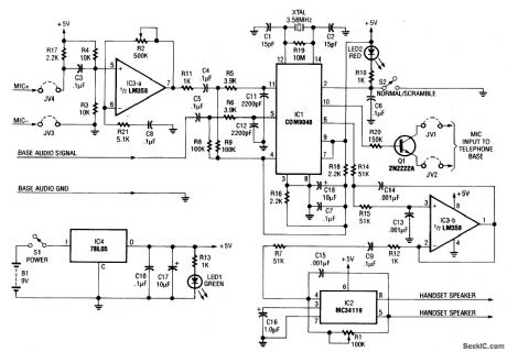
This circuit uses the usual speech inversion algorithm, implementing it with a COM9046 ASIC. This unit is designed to fit be-Lween the handset and base of a standard telephone. It is powered by a 9-V battery. (View)
View full Circuit Diagram | Comments | Reading(0)
TELEPHONE_HOLD_CIRCUIT
Published:2009/6/24 3:46:00 Author:Jessie
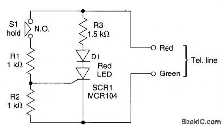
When the hold button S1 is pressed, SCR1 fires via R1 and R2, firing SCR1, and seizing the line via the path through R3, D1, and SCR1. (View)
View full Circuit Diagram | Comments | Reading(0)
TELEPHONE_RING_SIGNAL_DETECTOR
Published:2009/6/24 3:45:00 Author:Jessie
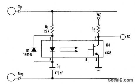
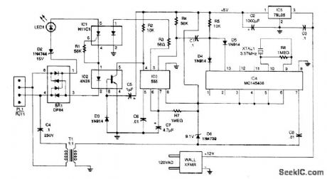
Discrirrtinating between telephone-ring signals on a phone line can be accomplished by using dedicated ICs, such as AT&T's LB1006AB or Texas Instruments' TMS1520A. However, if the system already is using a microcontroller, those dedicated chips can be replaced with simpler hardware and a few bytes of code.Looking at the setup, the ringing voltage pulses the optoisolator's LED, which, in turn, pulses the low-asserted RD line to the microcontroller. The firmware analyzes the pulses to determine whether a valid ringing signal is present.The frequency limits of a valid signal are 20 to 80 Hz, which is modulated 2 seconds on and 4 sec-onds off (with distinctive ringing, though, this cadence can vary). Therefore, the simplest analysis is to count down at least 20 pulses of RD in 1 second.The routine could be expanded to determine what type of ring signal is present in a distinctive ring setting. Such a system could switch the phone line to various output jacks. As a result, several phone devices could use the same line without first picking up the line to determine if it's avoice, fax, or data call. (View)
View full Circuit Diagram | Comments | Reading(3579)
PHONE_HELPER
Published:2009/6/24 3:44:00 Author:Jessie
This phone-line simulator uses a 60-Hz transformer instead of a ring generator. The dial tone is provided by an NE555 astable oscillator. (View)
View full Circuit Diagram | Comments | Reading(4904)
TELEPHONE_AUDIO_INTERFACE
Published:2009/6/24 3:39:00 Author:Jessie
The telephone audio interface-essentially, a simple isolation/couple circuit-isolates the phone line from any connected audio circuit without presenting any danger to the phone line, the equip-rnent, or the user. (View)
View full Circuit Diagram | Comments | Reading(6387)
BELL_SYSTEM_202_DATA_ENCODER
Published:2009/6/24 3:38:00 Author:Jessie
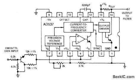
The AD537 is well-suited for frequency-shift modulator and demodulator applications. Requir-ing little power, it is especially appropriate for using phone-line power. The Bell-System 202 data en-coder shown here delivers the mark frequency of 1.2 kHz with the data input low. When the input goes high, the timing current increases to 165 μA and generates the space frequency of 2.2 kHz. The trim shown provides a ±10% range of frequency adjustment. The output goes to the required band-pass filter before transmission over a public telephone line. A complementary demodulator is easy to implement. (View)
View full Circuit Diagram | Comments | Reading(1323)
TELEPHONE_SCRAMBLER
Published:2009/6/24 3:36:00 Author:Jessie
This circuit uses the usual speech inversion algorithm, implementing it with a COM9046 ASIC. This unit is designed to fit be-Lween the handset and base of a standard telephone. It is powered by a 9-V battery. (View)
View full Circuit Diagram | Comments | Reading(3085)
TELEPHONE_CALL_RESTRICTOR
Published:2009/6/24 3:34:00 Author:Jessie
This circuit is designed to restrict phone calls with the area codes: 900, 976, and 540. This device uses a microcontroller to compare the DTMF decoded tones with telephone numbers stored in EEP-ROM (IC3). This device requires a programmed microcontroller. Software and details of program-ming can be found in the original magazine article. (View)
View full Circuit Diagram | Comments | Reading(2285)
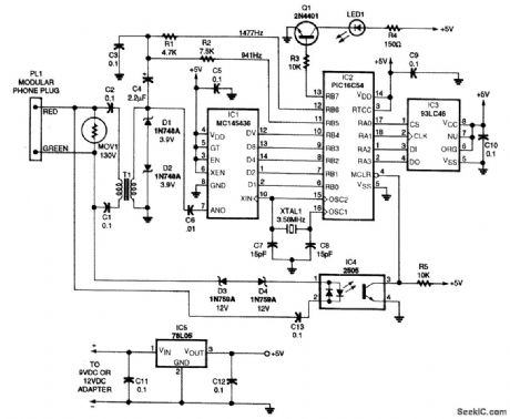
CALLER_ID_CIRCUIT
Published:2009/6/24 3:33:00 Author:Jessie
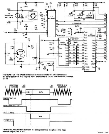
This circuit requires programming of the microcontroller. Software information is available from the reference in the original article. (View)
View full Circuit Diagram | Comments | Reading(0)
DISPLAY_BOARD_FOR_RADAR_GUN
Published:2009/6/24 3:17:00 Author:Jessie
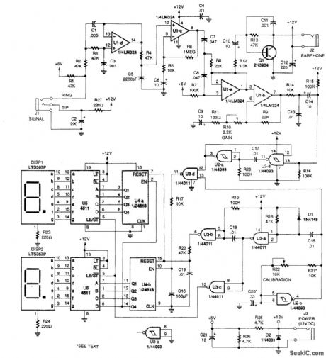
This circuit takes signal (doppler) from a radar,un, amplifies and limits it, and feeds the frequency into a counter (U4) and display circuit (DISP1, DISP2,U5,U6). Counter calibration is set by clock circuit U2B. Calibration is obtained via R21 and R22. R21 can be changed if kilometers/hour readout is desired. (View)
View full Circuit Diagram | Comments | Reading(0)
125_MHz_LOGIC_PROBE
Published:2009/6/24 3:06:00 Author:Jessie

This logic probe features either high-low (LED) indication or latching operation. When S1 closed, the indication of a pulse is latched and the red LED1 stays on. Piezoelectric buzzer BZ1 used as a beeper to sound that a logic high is preset. (View)
View full Circuit Diagram | Comments | Reading(2310)
MOTOR_DIRECTION_CONTROL_USING_DISCRETE_TRANSISTORS
Published:2009/6/24 3:01:00 Author:Jessie
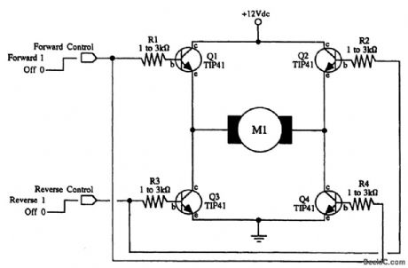
For best operation, mount the transistors on heatsinks. The transistors specified are fine for small hobby motors, or up to about 6 volts dc and between 800 and 1000 rnA. M1 is a srnall hobby motor. (View)
View full Circuit Diagram | Comments | Reading(1580)
STEPPER_MOTOR_ENCODER_CIRCUIT
Published:2009/6/24 3:00:00 Author:Jessie
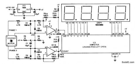
This circuit translates shaft rotation and direction to a readout on an LED display. A stepper motor is used as an encoder. (View)
View full Circuit Diagram | Comments | Reading(3693)
STEPPER_MOTOR_AS_SHAFT_ENCODER
Published:2009/6/24 2:59:00 Author:Jessie
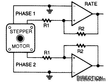
To use a stepper as a shaft encoder, the out-put signals must be converted to square waves with a pair of voltage comparators. (View)
View full Circuit Diagram | Comments | Reading(2517)
LOW_COST_20_W_AUDIO_AMPLIFIER
Published:2009/6/24 2:59:00 Author:Jessie
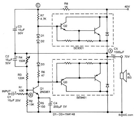
This simple inexpensive audio amplifier can be constructed using a couple of TO-220 monolithic Darlington transistors for the push-pull output stage. Frequency response is flat within t dB from 30 Hz to 200 kHz with typical harmonic distortion below 0.2%. The amplifier requires only 1.2 Vrms, for a full 20 W output into an 8 ohm load. Only one other transistor is needed, the TO-92 low-noise high-gain 2N5961 (Q1), to provide voltage gain for driving the output Darlingtons. Its base (point B) is the tie point for ac and dc feedback as well as for the signal input. Input resistance is 10 K. The center voltage at point A is set by adjusting resistor R4. A bootstrap circuit boosts the collector supply voltage of Q1 (point C) to ensure sufficient drive voltage for 6)2. This also provides constant voltage across R7, which therefore acts as a current source and, together with diodes Dl-D3, reduces low-signal crossover distortion. (View)
View full Circuit Diagram | Comments | Reading(0)
GUNSHOT_SOUND_EFFECTS_GENERATOR
Published:2009/6/24 2:46:00 Author:Jessie
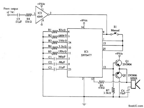
Gunshot sound-effects generator built around a Texas Instruments SN76477 sound chip. An in-put pulse causes IC1 to generate a gunshot sound. (View)
View full Circuit Diagram | Comments | Reading(3641)
| Pages:80/126 At 206162636465666768697071727374757677787980Under 20 |
Circuit Categories
power supply circuit
Amplifier Circuit
Basic Circuit
LED and Light Circuit
Sensor Circuit
Signal Processing
Electrical Equipment Circuit
Control Circuit
Remote Control Circuit
A/D-D/A Converter Circuit
Audio Circuit
Measuring and Test Circuit
Communication Circuit
Computer-Related Circuit
555 Circuit
Automotive Circuit
Repairing Circuit