
Index 81
800_Hz_OSCILLATOR
Published:2009/6/24 2:46:00 Author:Jessie
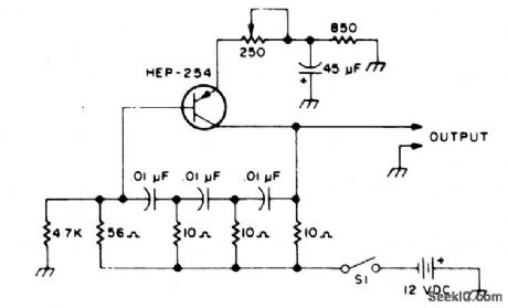
The following transistors may be used: HEP-254, O.C-2, SK-3004, AT30H. To increase the frequency, decrease the value of the capacitors in the ladder network. (View)
View full Circuit Diagram | Comments | Reading(1532)
ELECTRONIC_WIND_CHIME
Published:2009/6/24 2:45:00 Author:Jessie
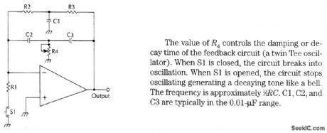
The value of R4 controls the damping or decay time of the feedback circuit (a twin Tee oscillator). When S1 is closed, the circuit breaks into oscillation. When S1 is opened, the circuit stops oscillating generating a decaying tone like a bell.The frequency is approximately 1/2 RC. C1, C2, and C3 are typically in the 0.01-μF range. (View)
View full Circuit Diagram | Comments | Reading(1699)
PHASE_SHIFT_OSCILLATOR
Published:2009/6/24 2:45:00 Author:Jessie
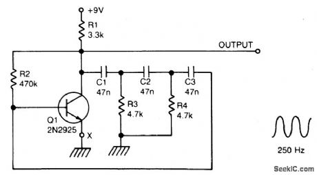
A single transistor makes a simple phase shift oscillator. The output is a sine wave with distortion of about 104. The sine wave purity can be increased by putting a variable resistor (25 ohms) in the emitter lead of Q1 (x). The resistor is adjusted so the circuit is only just oscillating, then the sine wave is relatively pure. Operating frequency may be varied by putting a 10 K variable resistor In serles with R3,Or by changing C1,C2,and C3.Making C1,2, 3 equal to 100 nF will halve the operatingfrequency,Operating frequencycanalso bevoltage controlled by a FET In serles with R3,Or optically controlled by an LDR In serles with R3. (View)
View full Circuit Diagram | Comments | Reading(0)
ROBOTIC_CHATTER_SOUND_GENERATOR
Published:2009/6/24 2:44:00 Author:Jessie

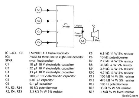
This circuit simulates sound effects of a robot, for toy or novelty applications.
(View)
View full Circuit Diagram | Comments | Reading(0)
TONE_ENCODER
Published:2009/6/24 2:35:00 Author:Jessie
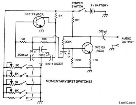
A basic twin-T circuit uses resistors for accurately setting the frequency of theoutput tones, selected by pushbutton. Momentary switches produce a tone only when the button is depressed. (View)
View full Circuit Diagram | Comments | Reading(2558)
PHASE_SHIFT_OSCILLATOR
Published:2009/6/24 2:33:00 Author:Jessie
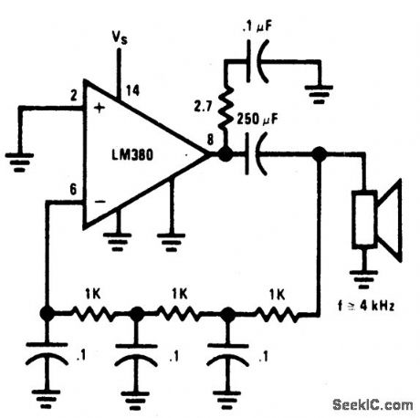
ircuit uses a simple RC network to pro-duce an exceptionally shrill tone from a minia-ture speaker. With the parts values shown, the circuit oscillates at a frequency of 3.6 kHz and drives a miniature 2 1/2 speaker with ear-piercing volume. The output waveform is a square wave with a width of 150 pts, sloping rise and fall times, and a peak-to-peak amplitude of 4.2 volts (when powered by 9 volts). Current drain of the oscillator is 90 mA at 9 volts, and total power dissipation at this voltage is 0.81 watt, which is well below the 1.25 watts the 14-pin version will absorb (at room temperature) before shutting down. (View)
View full Circuit Diagram | Comments | Reading(3727)
WIEN_BRIDGE_SINE_WAVE_OSCILLATOR
Published:2009/6/24 2:32:00 Author:Jessie

Using the 2N5457 JFET as a voltage vari-able resistor in the amplifier feedback loop, produces a low distortion, constant amplitude sine wave getting the amplifier loop gain just right. The LM103 zener diode provides the voltage reference for the peak sine wave amplitude. (View)
View full Circuit Diagram | Comments | Reading(0)
EASILY_TUNED_SINE_SQUARE_WAVE_OSCILLATORS
Published:2009/6/24 2:31:00 Author:Jessie
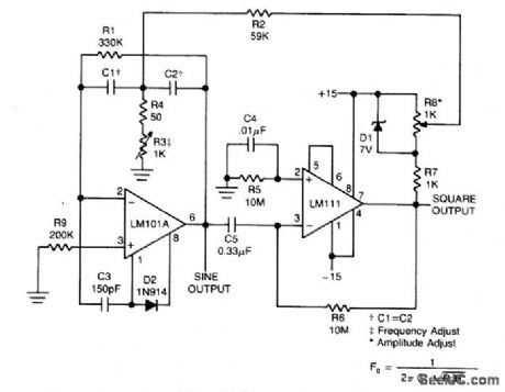
This circuit will provide both a sine and square wave output for frequencies from below 20 Hz to above 20 kHz. The frequency of oscillation is easily tuned by varying a single resistor. (View)
View full Circuit Diagram | Comments | Reading(1364)
SINE_WAVE_OSCILLATOR
Published:2009/6/24 2:31:00 Author:Jessie
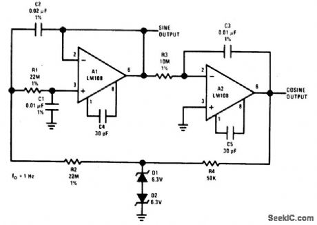
The oscillator delivers a high-purity sinusoid with a stable frequency and amplitude. (View)
View full Circuit Diagram | Comments | Reading(1724)
AUDIO_OSCILLATOR
Published:2009/6/24 2:30:00 Author:Jessie

Almost any transistor will work. R1 and C1 will vary the tone. (View)
View full Circuit Diagram | Comments | Reading(330)
CW_IDENTIFIER_WITH_SINE_WAVE_AUDIO_OUTPUT
Published:2009/6/24 2:29:00 Author:Jessie
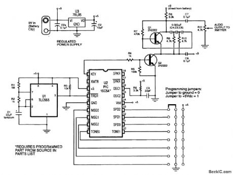
This identifier can be used to drive a hidden transmitter in a radio fox hunt activity, where the object is to locate a hidden transmitter. (View)
View full Circuit Diagram | Comments | Reading(1963)
Monolithic Stereophonic Receiver Integrated Circuit of CXA1129N
Published:2011/7/22 21:51:00 Author:Michel | Keyword: Receiver Integrated Circuit
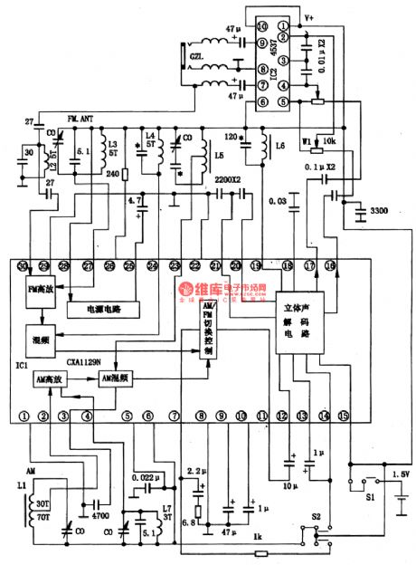
CXA1129N is monolithic stereophonic receiver integrated circuit produced by Sony.It integrates the am, FM stereo radio functions.And it saves power which can be used for one month with one A battery.
First,CXA1129N typical work voltage is 1.5V and the work current is 8mA.
Second,CXA1129N integrated block inside circuit block diagram is shown as figure 1. Figure 1 CXA1129N insdie circuit block diagram of integrated block and typical application circuit.
Third,Pins Functions and Data
CXA1129N uses 30 feet double row flat type plastic package with small size,the length is 10 mm and the width is 5.5 mm/ (View)
View full Circuit Diagram | Comments | Reading(3646)
PIEZO_MOTOR_DRIVE
Published:2009/6/23 22:06:00 Author:Jessie
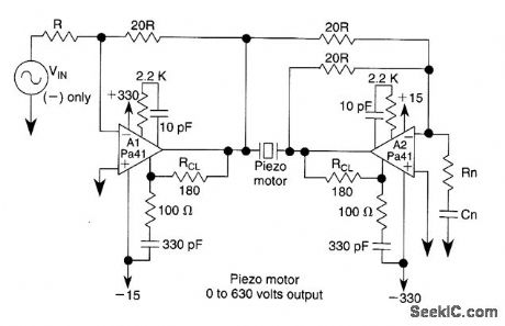
Using two Apex Microtechnology PA41 devices in a bridge circuit, this piezo motor driver delivers 0- to 630-V output. (View)
View full Circuit Diagram | Comments | Reading(2417)
PWM_MOTOR_DRIVE_CIRCUIT
Published:2009/6/23 21:56:00 Author:Jessie
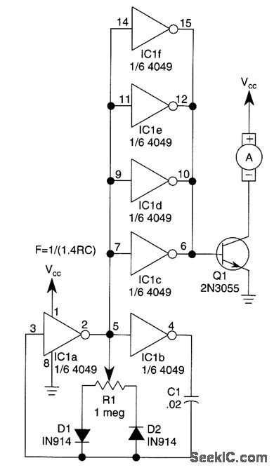
This circuit will drive a small dc motor over a wide range of speeds without stalling by controlling the duty cycle of the motor, rather than the supply voltage. (View)
View full Circuit Diagram | Comments | Reading(1086)
MICROWAVE_MOTION_DETECTOR
Published:2009/6/23 21:47:00 Author:Jessie
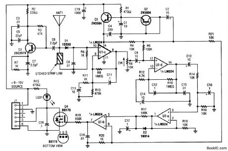
Operating at around 1.1 GHz, the detector senses field disturbance in the neighborhood of the antenna. The Doppler signal from detector D1 is amplified and drives a power MOSFET switch. The antenna is a short (2 to 3 ) length of wire. (View)
View full Circuit Diagram | Comments | Reading(2185)
MODULATOR_FOR_VIDEO
Published:2009/6/23 4:47:00 Author:Jessie
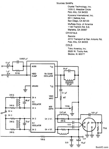
This circuit uses an LM2889 and a saw filter for use as a TV modulator. (View)
View full Circuit Diagram | Comments | Reading(637)
TWO_TONE_SIREN
Published:2009/6/23 4:45:00 Author:Jessie
IC1 generates the main siren tone while IC2 generates a low-frequency square wave, switching IC1 between two different tones. (View)
View full Circuit Diagram | Comments | Reading(0)
Monolithic Voice Record-replay Intergarted Circuit
Published:2011/7/22 21:38:00 Author:Michel | Keyword: Monolithic Voice Record-replay , Intergarted Circuit
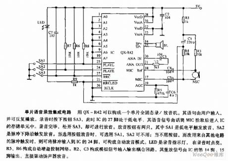
Monolithic Voice Record-replay Intergarted Circuit
QX-R42 can constitute a monolithic solid recorder and its sentence is input by users and played repeatedly.Please press button SA3 when you record and at the time,27 feet of the IC is in low PWL and voice signals enter storage unit via Microphnone,MIC.Plesae loosen the button and it can play the voice after finishing recording.There are two palyback buttons.SA1 is low PWL triggering playback.SA2 caues tirggering playback by pulse falling.SA1 can be chosen and SA2 is not used when we choose playback button.When we choose to use other circuit'spulsetriggering but button and the pulse will be input IC's 24 feet and it constitute automatic playback mode.LED is recording indicating light and it sparks during the recording process.R5 and R6 constitute automatic gain control net.R2 and C3 constitute analog signals which iuput and output coupling loop.Thus the 14th and 15th feet output playback signals and the speaker is drived to playback directly. (View)
View full Circuit Diagram | Comments | Reading(741)
WAILING_SOUND_GENERATOR
Published:2009/6/23 4:45:00 Author:Jessie
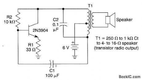
In this circuit, C2 and T1 determine the tone generated and C1/R1 control the blocking rate. The signal produced is an interrupted tone, like a police whistle or toy ray gun, depending on C1 and C2. (View)
View full Circuit Diagram | Comments | Reading(727)
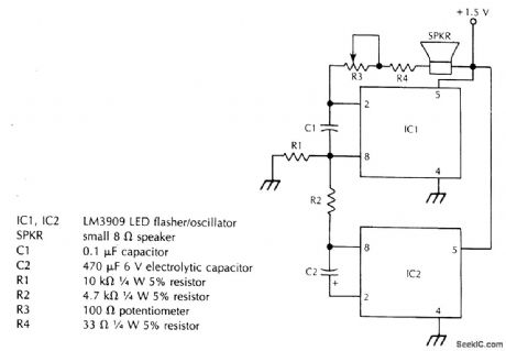
ELECTRONIC_SIREN
Published:2009/6/23 4:44:00 Author:Jessie
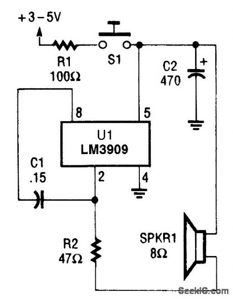
In this circuit, the LM3909 is used in a simple electronic siren. When S1 is closed, C2 begins to charge rapidly through RI. When the charge on C2 reaches about 1 V, the oscillator starts. As the voltage across C1 increases toward +7, the oscillator's output frequency also increases. Releasing (opening) S1 removes power from the circuit. The oscillator continues to operate, with a decline in output volurrte and frequency until C1 discharges to about the l-V level.Experiment with the siren circuit by selecting different R1/C2 combinations to obtain a desired rise and fall output. Change the value of C1 to vary the oscillator's frequency. Keep the value of R2 at or above 47Ω to protect the IC from drawing too much current. (View)
View full Circuit Diagram | Comments | Reading(0)
| Pages:81/126 At 2081828384858687888990919293949596979899100Under 20 |
Circuit Categories
power supply circuit
Amplifier Circuit
Basic Circuit
LED and Light Circuit
Sensor Circuit
Signal Processing
Electrical Equipment Circuit
Control Circuit
Remote Control Circuit
A/D-D/A Converter Circuit
Audio Circuit
Measuring and Test Circuit
Communication Circuit
Computer-Related Circuit
555 Circuit
Automotive Circuit
Repairing Circuit