
Index 101
MIC Bias Circuit-1.5km Single-Tube FM Radio MIC Transmitter Circuit
Published:2011/6/10 21:34:00 Author:Robert | Keyword: MIC, Bias Circuit, 1.5km, Single-Tube, FM, Transmitter
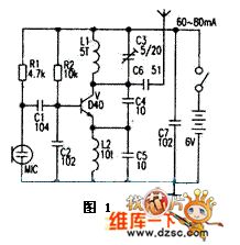
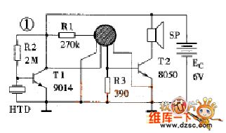
The picture 1 is a typical 1.5km single-tube FM radio MIC transmitter circuit. This circuit's key components is emission triodes which always are the D40, D50, 2N3866 and so on. Its working circuit is 60-80mA.
In amateur case it is easy to make a successful low-power radio circuit with 88~108MHz FM frequency range. This circuit has sinple single-tube transmitter circuit and also uses the integrated stereo transmitter circuit. It is mainly used for FM radio headset, wireless telephone recording forwarding, remote control, wireless alarm, monitoring, data ransmission and campus FM radio and so on.
(View)
View full Circuit Diagram | Comments | Reading(2962)
The speed governing fan circuit
Published:2011/6/3 0:15:00 Author:Seven | Keyword: speed governing fan
View full Circuit Diagram | Comments | Reading(626)
The circuit of fans with display functions
Published:2011/6/6 23:09:00 Author:qqtang | Keyword: fans, display
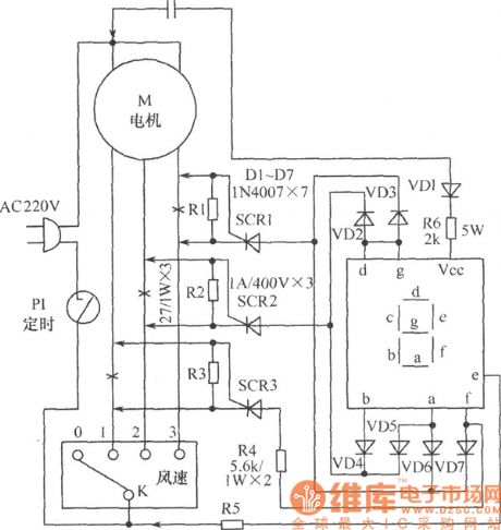
The principle circuit is shown in the following figure, it cuts off the X spots of the speed phase lines in turn, and links to the step-down resistors of R1~R3. When the wind speed switch K is on some gear, the conducting current provides the LED digital pipe with power by VD2~VD7, and now the gear number can be displayed. When the gear switch K is shifting, the coil circuit is cut off.
(View)
View full Circuit Diagram | Comments | Reading(586)
The multi-Line answering racer circuit
Published:2011/6/7 11:22:00 Author:qqtang | Keyword: multi-Line answering racer
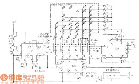
See as the figure, this is a multi-Line answering racer circuit, whose characters are as follows:(1) the number of lines is large, which can be added to 10 (there are 6 in the figure); (2) it is fixed with self-made digital large screen display team No., the image is direct, and the screen can be used for thousands of audiences; (3) it is adapted with the pulse scanning method, and there won't be more than one team answering at the same time; (4) quality-price ratio is high. The circuit is made of 3 CMOS integrated circuits and some common elements, which is low-cost.Elements selecting: IC1 is a 6 NAND CD4069. (View)
View full Circuit Diagram | Comments | Reading(581)
The caller number display device circuit
Published:2011/6/7 10:36:00 Author:qqtang | Keyword: caller number, display device
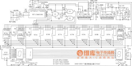
The device works with the phones that haven't got the functions of display, which can display caller number so that people can check if the called number is right.See as the circuit, the dialing generates DTMF signals and the signals are decoded by decoder CM8870P1(IC1), then the phone number BCD codes are generated, the BCD code of each number is locked in the according latch. This circuit can display 10 bit phone numbers. The first bit of the number is locked in IC5A(1/2CD4508), the second is locked in IC5B, etc. (View)
View full Circuit Diagram | Comments | Reading(800)
TC901--the integrated circuit of fan single chip microcomputer
Published:2011/6/7 11:08:00 Author:qqtang | Keyword: integrated circuit, single chip microcomputer
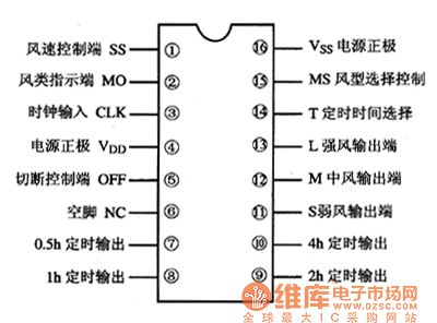
TC901 is a microcomputer integrated circuit of fan single chip produced by Toshiba, which is widely used in speed adjusting and power adjusting of all kinds of fans and household appliances.1.function featuresTC901 includes order decoding circuits, clock circuits, indicator drive circuitS, wind speed adjusting circuits and so on.2.pin functionsTC901 is in 16-pin dual in-line package, whose pin functions are shown in Figure 1.Figure 1. The pin functions of TC901
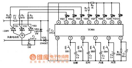
3.typical application circuitFigure 1. The typical application circuit of TC901
(View)
View full Circuit Diagram | Comments | Reading(934)
The main character parameter table of CL300 LED +/- symbol display elements
Published:2011/6/8 7:16:00 Author:qqtang | Keyword: character parameter, symbol display elements
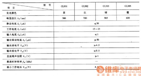
CL300 LED±symbol display elements characterize low-power, high reliability, long lifespan and so on, which is used in digital equipment, instruments and all kinds of digital devices, + and - are the indication. The main characteristic parameters are listed in the table. Table:The main characteristic parameters of CL300 LED +/- symbol display elements
(View)
View full Circuit Diagram | Comments | Reading(685)
A8777N--the multi-line electric switch shifting integrated circuit
Published:2011/6/8 7:30:00 Author:qqtang | Keyword: multi-line electric switch, integrated circuit
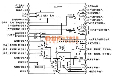
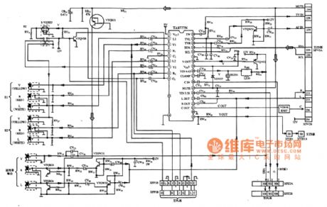
A8777N is a multi-line electric switch shifting integrated circuit, which is widely used in audio systems and video systems.1.functions featuresA8777N contains I2C general connector circuit, clamper circuit, multi-line electric circuit and other additional circuit. This circuit can shift all kinds of signals under the control of I2C general line signals.2.the internal circuit and pin functionsThe internal circuit and pin functions of A8777N are shown in figure 1.Figure1 The internal circuit and pin functions of A8777N
(View)
View full Circuit Diagram | Comments | Reading(1440)
Electronic rodent repeller circuit diagram 5
Published:2011/6/7 4:40:00 Author:Lucas | Keyword: Electronic rodent repeller
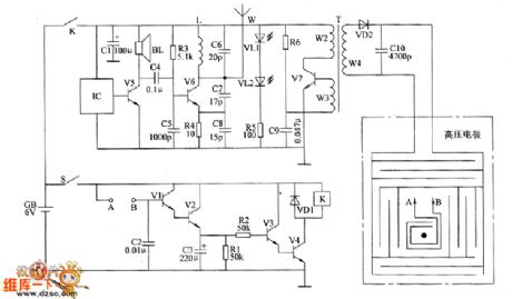
The electronic rodent repeller circuit is composed of the trigger control circuit, sound and light alarm circuit, wireless transmitter circuit and high-voltage generator output circuit, and the circuit is shown as the chart. Control circuit is composed of trigger sensor (the two electrodes between A and B ), transistors V1 ~ V4, resistors R1, R2, capacitors C2, C3, diode VD1 and relay K. Sound and light alarm circuit is composed of the music integrated circuit IC, transistor V5, speaker BL, resistor R5 and LEDs VL1, V12. Wireless transmitter circuit consists of resistors R3, R4, capacitors C4 ~ C8, inductor L, transistor V6 and antenna W. High-voltage generator output circuit consists of the resistor R6, capacitors C9, C1O, step-up transformer T, the transistor V7, diode VD2 and high-voltage electrodes.
(View)
View full Circuit Diagram | Comments | Reading(1006)
Electronic rodent repeller circuit diagram 6
Published:2011/6/7 4:40:00 Author:Lucas | Keyword: Electronic rodent repeller
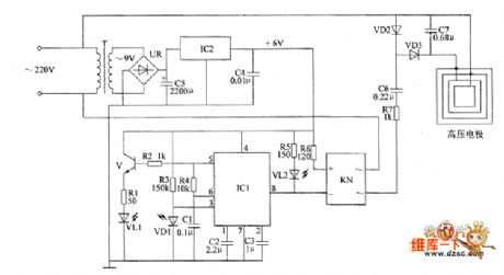
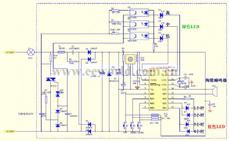
The electronic rodent repeller circuit is composed of the power circuit, infrared control circuit and high-voltage circuit, and the circuit is shown as the chart. Power circuit is composed of the power transformer T, bridge rectifier UR, filter capacitors C4, C5, and three-terminal voltage regulator integrated circuit IC2. Infrared control circuit consists of infrared light-emitting diode VL1, infrared photodiode VD1, transistor V, resistors R1 ~ R6, capacitors C1 ~ C3, integrated circuit IC1, light-emitting diode VL2 and solid-state relay KN. High voltage circuit is composed of the solid-state relay KN, resistor, capacitors C6, C7, diodes VD2, VD3, and high-voltage electrodes. 220V AC voltage is bucked by T, rectified by UR, filtered by C5 and stabilized by IC2 to provide +6 V voltage for infrared control circuit.
(View)
View full Circuit Diagram | Comments | Reading(1028)
Electronic rodent repeller circuit diagram 4
Published:2011/6/7 4:39:00 Author:Lucas | Keyword: Electronic rodent repeller
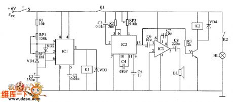
The electronic rodent rodent repeller circuit is composed of the time oscillator, mew generator, audio power amplifier and flash control circuit, and the circuit is shown as the chart. Oscillator circuit is composed of the time base timer integrated circuit IC1, resistor R1, potentiometers RP1, RP2, diodes VD1 ~ YD3, capacitors C1, C2, and relay K1. Mew generator is composed of the sound generator circuit IC IC2, resistor R2, potentiometer RP3 and capacitors C3 ~ C5. Audio power amplifier is composed of the power amplifier integrated circuit IC3, capacitors L6 ~ C8 and speaker BL. Flash control circuit consists of transistor V, resistor R3, relay K2, diode HL and small bulb VD4.
(View)
View full Circuit Diagram | Comments | Reading(1109)
Electronic rodent repeller circuit diagram 2
Published:2011/6/7 4:39:00 Author:Lucas | Keyword: Electronic rodent repeller

The electronic rodent repeller circuit is composed of the timer circuit, mew generator and power amplifier and other components, and the circuit is shown as the chart. Timer circuit is composed of a time-base integrated circuit IC1 and the non-steady-state multivibrator composed of the related external components. Mew generator consists of integrated circuit IC2 and transistors V and so on. Power amplifier consists of integrated circuit IC3, and related peripherals RC components. R1 ~ R5 use 1/4W or 1/8W carbon film resistors. RP1 and RP2 can choose small solid-type potentiometer or variable resistor WH7. C1, C3 ~ C7 select aluminium electrolytic capacitor with the voltage in 16V; C2 and C8 select ceramic capacitors. VD1 and VD2 use 1N4148 silicon switching diodes. V uses 590I3 or 3DG12 silicon NPN transistor.
(View)
View full Circuit Diagram | Comments | Reading(1273)
Logic Status Probe Circuit
Published:2011/5/21 1:50:00 Author:Robert | Keyword: Logic Status, Probe
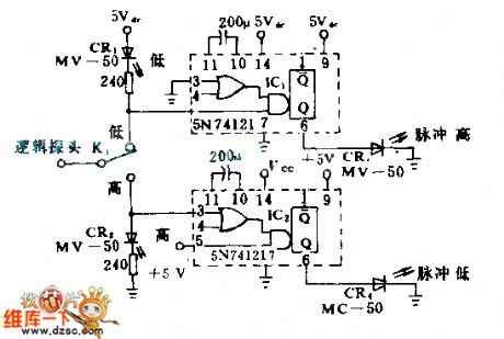
This circuit is used in the application cases where has low repeating frequency and also has very narrow single pulses. For example, the computer's interface and logic control system's signals. The monostable circuit change the pulses as norrow as 50ns to be extended, so that the LED's lighting or not can be seen clearly. If the under-test circuit's stable status is low voltage level, and K1 is put at low position, the CR1 would light. If it is put at high position and the circuit's stable status is high voltage level, the CR2 would light. The other two LED means the pulse signals in the stable signals.
(View)
View full Circuit Diagram | Comments | Reading(695)
acoustic control four-tone doll electric principle circuit
Published:2011/6/7 19:40:00 Author:John | Keyword: acoustic control four-tone doll
This circuit uses the FL-11 blocks without few external components. The device is simple. The completed acoustic control board is connected to the speaker with 2 1 / 4 inches. Put the unit into the box and add 4 5-storm cells and its support outside. Power on and push the entire device into the doll’s body. Once clapped, its voices of crying or shouting for father and mother can achieve the degree of real ones. This circuit is generally needed to be debugged because it is able to succeed.
(View)
View full Circuit Diagram | Comments | Reading(622)
HY-2 music IC typical application circuit
Published:2011/6/7 10:30:00 Author:John | Keyword: music IC
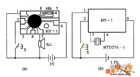
HY-2 music IC has three pieces of music inside. When the circuit is triggered, the output music signal also changes accordingly. When the trigger terminal is connected with the trigger level, the circuit will affect to repeat preset three songs again and again until the trigger level stops. HY-2 music IC typical application circuit is as shown below.
(View)
View full Circuit Diagram | Comments | Reading(683)
The digital display answering racer circuit
Published:2011/6/7 11:52:00 Author:qqtang | Keyword: digital display, answering racer
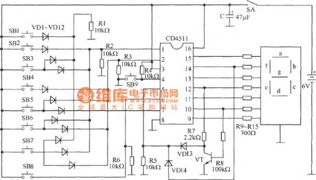
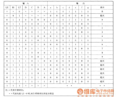
In the figure, the digital display answering racer adapts the digital pipe as the display, which can make players and audiences see the results, so the transparence is good.Working principles: digital display answering racer circuit is shown in the figure. CD4511 is main part of the digital display answering racer. This is a BCD-7 lock/decoder/drive circuit, whose 1, 2, 6 and 7 pins are the input terminal, and 9~15 pins are the display output terminals. 3-pin LT is the detection terminal, when it is 0 , the output is 1 .
(View)
View full Circuit Diagram | Comments | Reading(679)
Electronic rodent repeller circuit diagram 3
Published:2011/6/3 2:15:00 Author:Lucas | Keyword: Electronic rodent repeller
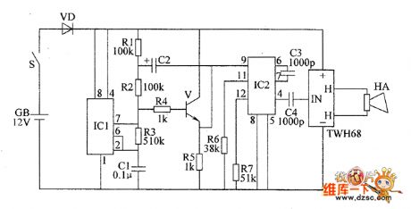
The electronic rodent repeller circuit is composed of the astable multivibrator, emitter follower converter, voltage controlled oscillator (YC0), driver amplifier circuit and the piezoelectric ceramic speaker HA with super loudness, and the circuit is shown as the chart. Astable multivibrator integrated circuit is composed of the time-base integrated circuit IC1, resistors R1 ~ R3, capacitor C1 and so on. Emitter follower converter is composed of the transistor V and the bias components. Voltage-controlled oscillator (VCO) consists of the PLL IC IC2 and external RC components. Driver amplifier uses TWH68 special amplifier module (including power amplifier circuit and ferrite step-up transformer, etc.). R1 ~ R7 select 1/4W carbon film or metal film resistors resistors.
(View)
View full Circuit Diagram | Comments | Reading(930)
EW-8W electronic ballast circuit
Published:2011/5/31 8:01:00 Author:chopper | Keyword: electronic ballast

View full Circuit Diagram | Comments | Reading(1819)
Electronic rodent repeller circuit diagram 1
Published:2011/6/2 19:50:00 Author:Lucas | Keyword: Electronic, rodent repeller
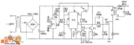
The electronic rodent control circuit is composed of infrared detection components, electronic switch, high-frequency oscillator circuit, high voltage generating circuit, sound alarm circuit and power components, and the circuit is shown as the chart. Electronic switch is composed of the transistor V1 and related peripheral components. High-voltage generating circuit is composed of the field-effect transistor VF, step-up transformer T2, diodes VD5 and VD6 and so on. High-frequency oscillator is composed of the IC2 and the related external components, and its working frequency is 15kHz. Sound alarm circuit consists of transistors V2 and V3, resistor R5, capacitor C4 and speaker BL and so on. R1 ~ R8 select 1/4W carbon film resistors. C1 and C2 select aluminium electrolytic capacitors with the voltage in 16V; C3 and C4 select monolithic capacitors.
(View)
View full Circuit Diagram | Comments | Reading(1170)
Isolated Two-Wire Current Loop Circuit (XTR101, ISO100)
Published:2011/5/20 9:35:00 Author:Robert | Keyword: Isolated, Two-Wire, Current Loop
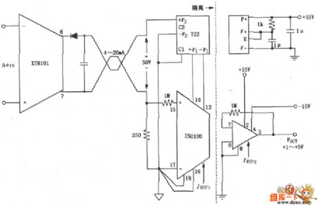
As shown in the picture below, this circuit uses the XTR101 in conjunction with isolated amplifier ISO100 to change and amplify the 4~20mA current to be +1~+5V output voltage. At the same time it should have isolation on the power. This circuit has a excellent anti-jamming feature, which can be used in the case of long-distance signal transmission or the scene where has a large disturbance.
(View)
View full Circuit Diagram | Comments | Reading(837)
| Pages:101/126 At 20101102103104105106107108109110111112113114115116117118119120Under 20 |
Circuit Categories
power supply circuit
Amplifier Circuit
Basic Circuit
LED and Light Circuit
Sensor Circuit
Signal Processing
Electrical Equipment Circuit
Control Circuit
Remote Control Circuit
A/D-D/A Converter Circuit
Audio Circuit
Measuring and Test Circuit
Communication Circuit
Computer-Related Circuit
555 Circuit
Automotive Circuit
Repairing Circuit