
Index 100
Multiplex Switchig Method Driving Display Circuit
Published:2011/5/17 5:52:00 Author:Robert | Keyword: Multiplex Switching Method, Driving, Display
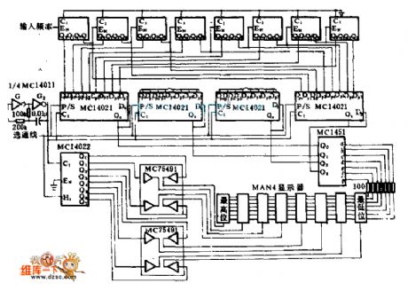
This circuit uses the battery to supply power. It takes a decode driver to drive the MAN-4 displayer'sseveral nixietubes one by one through the multiplex method, which can reduce the battery's power consumption. Because the readings saw by the human eye in the whole show cycle is still preserved impressions, it looks like the displayer being with a continuous display. The peak current of the displayer is 20mA, but every nixietube's electrified time is just 12.5% of the whole display cycle time. The four MC1402 8-bit shift registers lock and store the value caculated by the MC14515 counter and complete the multiplex switching function.
(View)
View full Circuit Diagram | Comments | Reading(660)
Typical Fan-Use Electronic Speed Governor Circuit
Published:2011/5/19 22:25:00 Author:Robert | Keyword: Fan-Use, Electronic, Speed Governor
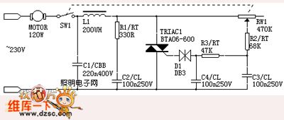
Most traditional fan speed governors are designedwith the capacitive voltage divider method. This method makes their adjustable gear stages less. By using the electronic control method shown in the picture below, it can get stepless speed regulating results. For the control to inductive fan it must make the bidirectional thyristor in parallel with a rc buffer network to limit the voltage rising rate (dv/dt). The c2 in the picture is used to limit the value beyond bidirectional thyristor's dv/dt value. The r1 is used to limit the c2's impact current when the thyristor is connected, and also it would weaken the damping oscillation between c2 and ll.
(View)
View full Circuit Diagram | Comments | Reading(1010)
Optocoupler SPDT Switch Circuit
Published:2011/6/7 18:48:00 Author:Robert | Keyword: Optocoupler, SPDT Switch
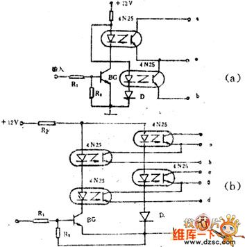
The optocoupler SPDT switch circuit is shown in the picture below.The picture (a) is SPDT switch circuit and the external connected diode D's function is to assure the od group channels connected and ob group channels disconnected when inputting positive pulse signal. The picture (b) is DPDT switch circuit. When there is no input signal, the BG is disconnected. The ob and od groups are disconnected and the oa and oc groups are connected. When the BG is connected (when having input signal), ob and od groups are connected and oa and oc groups are disconnected. They are suit in automatic control use and remote control equipment use.
(View)
View full Circuit Diagram | Comments | Reading(1839)
RTL/TTL Probe Circuit
Published:2011/5/27 7:56:00 Author:Robert | Keyword: RTL, TTL, Probe
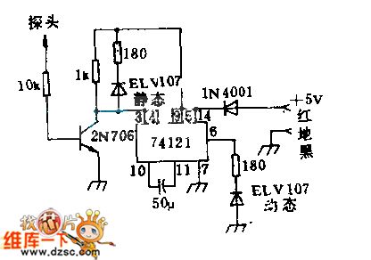
The static LED indicates the logic voltage level of the probe along its side. The dynamic LED's lighting indicates that there is a positive pulse or 1 pulse in the probe test port. Even the time is short while the pulse appearing, itcan still see the LED's lighting because this circuit has extended the pulse width to about 50ns. The pulse-extending device requires the input pulses is 100ns, 4V at least. The 1N4001 diode is used to prevent the damage caused by opposite connection of the power cord.
(View)
View full Circuit Diagram | Comments | Reading(688)
INA166 Signal And Power Supply Basic Connection Circuit
Published:2011/6/7 18:49:00 Author:Robert | Keyword: Signal, Power Supply, Connection
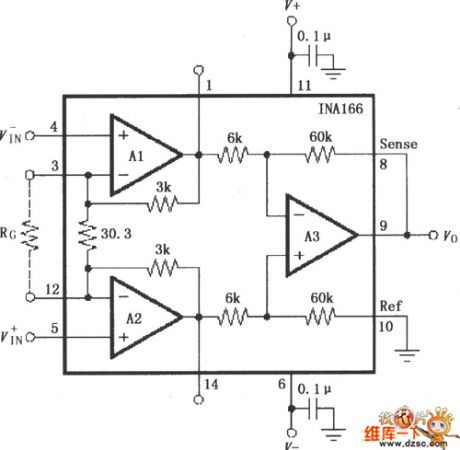
The INA166 Signal And Power Supply Basic Connection Circuit is shown in the picture below. The chip power supply port needs a 0.1uF tantalum capacitor for filtering. When in PCB layout it should make the tantalun capacitor as close to the chip power supply foot as possible. The output voltage detecting port Sense's connection and basic port Ref's connection must be connected with low resistance to assure high CMRR. If there is a 5Ω resistance in series it could reduce the CMRR. Its internal fixed gain is 2000. The input stage A1 and A2's gain is 200. The output stage A3's stage is 10. The amplifier gain can be changed by adding a gain-setting resistance RG between 3 foot and 12 foot. The gain would be G=2000+60000/RG.
(View)
View full Circuit Diagram | Comments | Reading(703)
Voice Modulation Optical Transmitter Circuit
Published:2011/5/27 7:57:00 Author:Robert | Keyword: Voice, Modulation, Optical, Transmitter
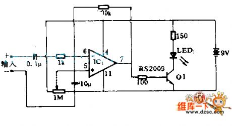
This circuit uses an operational amplifier and a transistor. According to the amplitudeof sound pickup device's output signal, it would do the amplitude modulation to the LED after its amplification. This circuit can be used in normal audio devices by optical receiver devices.
(View)
View full Circuit Diagram | Comments | Reading(2631)
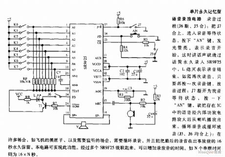
Monolithic Permanent Memory Type Voice Recording Circuit
Published:2011/6/3 10:18:00 Author:Michel | Keyword: Monolithic Permanent Memory, Voice Recording Circuit
View full Circuit Diagram | Comments | Reading(839)
Additional Circuit of Simple Anti-theft and Alarm Telephone
Published:2011/6/4 9:27:00 Author:Michel | Keyword: Anti-theft and Alarm Telephone, Additional Circuit
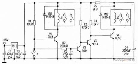
The author designs an additional circuit for anti-theft and alarm modified by finished telephone afer analyzing.Its material and facture are easy,cost is low,operation is convenient and it's safe and reliable.
Introduction to principleThe circuit is as the picture.K is reed pipe and V1 conducts,the fork reed switches's absorption of drive relays J1 is equal to that the telephone is off-hook . Another control signal amplifies via V2、V3 when it goes through R3 and C3's delay(RC in the picture is about 6s).V4 drive relay J2 is equal to redial key of the control telephone. (View)
View full Circuit Diagram | Comments | Reading(650)
Optical Coupling Phone Anti-theft Device Circuit
Published:2011/6/3 12:09:00 Author:Michel | Keyword: Optical Coupling, Phone Anti-theft Device Circuit
This transponder will tell your place or contact number to your friend when you friend calls you and you are outside.This transponder is safe and reliable and it will not be disturbed by busy signal.
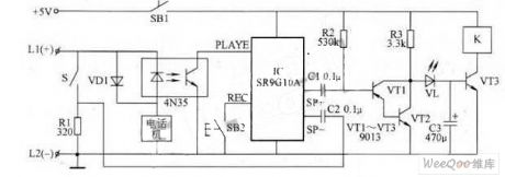
Work's Principle
The optical coupling phone answer circuit is showed as the pictureThe SRG10A is 10S audio record circuit.Please press SB2 to switch on the power.What you want to tell your friend will be recorded via carried in electret microphone(this is not be drawn in the picture) Please press SB1 when you go out.When it's static state, the clad pipe's collector voltage composed of VT1 and VT2 is around 0.65V and both VL and VT3 are off. (View)
View full Circuit Diagram | Comments | Reading(677)
NE602 Direct Variable Frequency Circuit
Published:2011/6/4 23:19:00 Author:Michel | Keyword: Direct Variable Frequency, Receiver Circuit
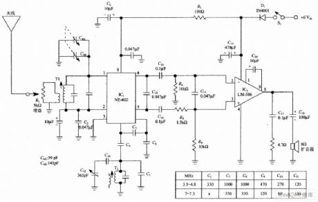
Push-pull output of NE-602(That's to say,tube feet 5 and feet 4 are used together)is more advanced than one-port output.Dillon points out that balanced output improves performance,especially its suppressionof AMBOB.At the same time,0.47μF capacitor is helpful to AM's breakthrough which connects across NE-602 output port. (View)
View full Circuit Diagram | Comments | Reading(8695)
The sickroom patient alarm screen circuit
Published:2011/6/10 1:00:00 Author:qqtang | Keyword: sickroom, alarm screen circuit
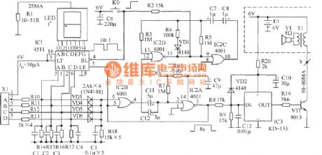
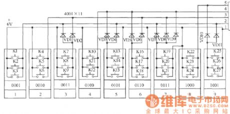
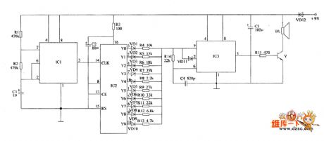
In the figure is a sickroom patient alarm screen circuit, whose acousto-optic terminal is installed in the nurse duty room. 1 bit number is displayed, and every 3 beds share a number, so a total of 27 patients are covered, which can meet the need of a small hospital. This circuit is only made of a common micro-power CMOS circuit IC1(4511) and IC2(4001), and a ding-dong door bell chip IC3(KD-1543). It is not only low-cost, which consumes only several microampere of power in waiting state, it is powered with two No.5 batteries (6v), but also doesn't need to install a power supply switch, so the users don't need to worry about about the power failure of the grid.
(View)
View full Circuit Diagram | Comments | Reading(662)
The digital display calendar clock circuit
Published:2011/6/10 3:54:00 Author:qqtang | Keyword: calendar clock
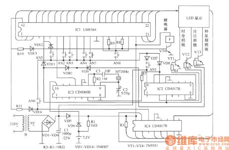
The circuit can display month, date, hour, minute, second and week, and they can be automatically switched, and it can ring for 2 times, it also has functions of sleep timing function in 59min. The calendar clock is punctual, easily adjusted, clear at night and easily made.Working principleThe core of the circuit is a PMOS mass integrated circuit LM8364. 4-pin is the selective terminal of 12/24 h, and the high LEV is 24h system. When 6-pin is suspended, the 60Hz time based signals are input from 7-pin, and when receiving the high LEV, the 50Hz time based signal should be input from 7-pin. (View)
View full Circuit Diagram | Comments | Reading(3524)
Electronic pests killing lamp circuit diagram 5
Published:2011/6/10 6:51:00 Author:Lucas | Keyword: Electronic , pests killing lamp
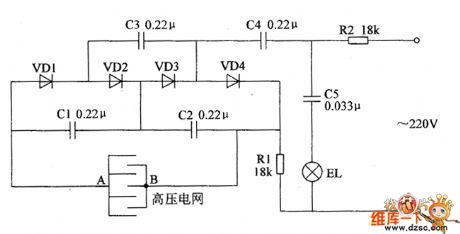
The electronic pests killing lamp circuit consists of high voltage generator circuit and lighting circuit, and the circuit is shown as the chart. Lighting circuit is composed of the resistor R2, capacitor C5 and trap lamp EL. High voltage generator is composed of the resistor R1, capacitors C1 ~ C4, diodes VD1 ~ VD4 and the high voltage grid ( the high voltage electrodes A, B ). One way of the AC 220V voltage limited and bucked by R2, C5 and added on the both ends of EL will make the light turn on; another way limited and bucked by R1, R2 and C1 ~ C4, 4 times voltage doubled and rectified by VD1 ~ VD4 will generate the DC high pressure voltage, which is added to the high voltage electrodes A, B and when the pests flies to EL and they would be killed by the DC high voltage. R1 and R2 select 2W metal film resistors. VD1 ~ VD4 use 1N4007 silicon rectifier diodes.
(View)
View full Circuit Diagram | Comments | Reading(1122)
Electronic pests killing lamp circuit diagram 4
Published:2011/6/10 6:40:00 Author:Lucas | Keyword: Electronic , pests killing lamp
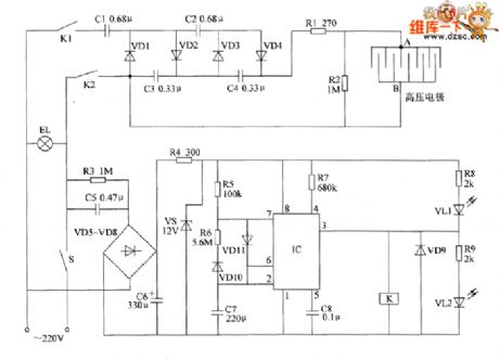
The electronic pests killing lamp circuit consists of the oscillator, control circuit, high voltage generator, LED indicating circuit and power supply circuit, and the circuit is shown as the chart. The oscillator circuit is composed of the time-base integrated circuit IC, resistors R5 ~ R7, diodes VD10, VD11 and capacitors C7, C8. Power supply circuit is composed of the capacitors C5, C6, resistors R3, R4, rectifier diodes VD5 ~ YD8 and voltage regulator diode VS. Control circuit consists of diode VD9, relay K and the pin 3 internal circuit of IC. High-voltage generator circuit consists of the capacitors C1 ~ C4, rectifier diodes VDI ~ VD4, resistors R1, R2, and high-voltage grid (high voltage electrodes A, B). LED indicating circuit consists of the resistors R8, R9, and light-emitting diodes VL1, VL2. R1 and R2 select 2W metal film resistors; R3 and R4 select 1W metal film resistors.
(View)
View full Circuit Diagram | Comments | Reading(1903)
The electronic birds repeller circuit diagram 3
Published:2011/6/10 11:22:00 Author:Lucas | Keyword: electronic, birds repeller
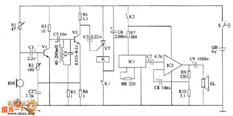
The electronic birds repeller circuit is composed of the pickup amplifier circuit, selective frequency amplifier circuit, trigger circuit, sound effect circuit and the audio amplifier circuit, and the circuit is shown as the chart. Pickup amplifier circuit consists of the microphone BM, preamp amplifier tube V1, resistors R1 ~ R3 and capacitors C1, C2. Selective frequency amplifier circuit is composed of the capacitors C3, C4, inductor L, resistors R4 ~ R6 and amplification tube V2. Trigger circuit is composed of the capacitors C5, C6, thyristor VT, relay Κ. Sound effect circuit is composed of the integrated circuit IC1 and resistor R8. Audio amplifier circuit is composed of the integrated circuit IC2, resistors R9, R1O, capacitors C8, C9 and speaker BL. RI and R2 use the sealed resistors; R3 ~ R1O choose 1/4W carbon film resistors. C1 ~ C3 and C6 ~ C9 choose aluminum electrolytic capacitors with the voltage in 16V.
(View)
View full Circuit Diagram | Comments | Reading(2431)
Electronic birds repeller circuit diagram 3
Published:2011/6/10 10:52:00 Author:Lucas | Keyword: Electronic, birds repeller

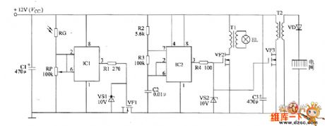
The electronic birds repeller circuit is composed of the solar charging circuit, light control electronic switch circuit, oscillator A, oscillator B, sound generator, audio amplifier output circuit and motor control circuit, and the circuit is shown as the chart. Solar charging circuit is composed of the solar cell GBI, isolation diode VD1 and the battery GB2. Light control electronic switch circuit consists of the light sensitive resistor RC and the electronic switch IC IC1. Oscillator A consists of the resistor R1, potentiometers RP1, RP2, diodes VD2, VD3, capacitors C1, C2, and time-based integrated circuit IC2. Sound generator circuit consists of resistors R2, R3, Zener diode VS and audio integrated circuit IC3. Audio amplifier output circuit is composed of the capacitors C3 ~ C5, audio power amplifier integrated circuit IC4 and speaker BL. Oscillator B consists of the resistors R4, R5, capacitors C6, C7, and time-based integrated circuit IC5.
(View)
View full Circuit Diagram | Comments | Reading(5615)
Electronic pests repeller circuit diagram 2
Published:2011/6/10 11:11:00 Author:Lucas | Keyword: Electronic , pests repeller
The electronic insect circuit is composed of the clock oscillator, counter, multivibrator and the audio output circuit, and the circuit is shown as the chart. The clock oscillator consists of the time-base IC IC1 and related peripheral components. The circuit can generate 1Hz clock signal, which is output form the pin 3 of IC1 and directly added to the pin 14 of IC2 (CLK). Multivibrator IC3 consists of the time-base IC IC3 and related peripheral components. It is used to produce 23 ~ 64kHz ultrasonic signals. Counter is composed of the integrated circuit IC2, diodes VD1 ~ VD10 and many RC components. All resistors use 1/4W carbon film resistors. C1 ~ C3 select the aluminium electrolytic capacitor with the withstand voltage being 16V; C4 uses ceramic capacitors. VD1 ~ VD11 select 1N4148 switching diodes; VD12 uses 1N4007 rectifier diode. IC1 and IC3 choose NE555 time-base integrated circuits.
(View)
View full Circuit Diagram | Comments | Reading(2468)
Electronic pests killing lamp circuit diagram 1
Published:2011/6/10 10:06:00 Author:Lucas | Keyword: Electronic , pests killing lamp
The electronic pests killing lamp circuit consists of the light control switch circuit, multivibrator, black light lamp drive circuit and high-voltage generator circuit, and the circuit is shown as the chart. Light control switch circuit consists of the photosensitive resistor RC, time-base integrated circuit IC1, potentiometer RP, resistor R1, Zener diode VS1 and field-effect transistor VF1. Multivibrator is composed of the time-base integrated circuit IC2, resistors R2, R3 and capacitor C2. Black light driver circuit consists of the resistor M, voltage regulator diode VS2, field-effect transistor YF2, pulse transformer T1 and black light EL. High-voltage generator circuit consists of the R4, VS2, and field-effect transistors VF3, high-voltage rectifier diode VD, and step-up transformer T2.
(View)
View full Circuit Diagram | Comments | Reading(1164)
Electronic pests killing lamp circuit diagram 2
Published:2011/6/10 10:32:00 Author:Lucas | Keyword: Electronic , pests killing lamp
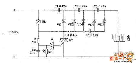
The electronic pests killing lamp circuit consists of the light control switch circuit and voltage doubling rectifier circuit, and the circuit is shown as the chart. Light control switch circuit is composed of the photoresistor RC, capacitor CO, lamp EL, resistor R, bidirectional trigger diode V and thyristor VT. Doubler rectifier circuit consists of the capacitors C1 ~ C5 and rectifier diodes VD1 ~ VD5. R uses 1W metal film resistor; RG uses the MOL series of photosensitive resistor, and the light resistance should be less than or equal to 3KΩ and dark resistance be greater than or equal to 5MΩ. CO selects polyester capacitor with the voltage being 160V ; C1 ~ C5 select the high-voltage paper capacitors or CBB capacitors with the voltage being 600V. VD1 ~ VD5 use 1N4007 silicon rectifier diodes. V uses DB3 or 2CTS series of bidirectional trigger diode. VT uses 3CTS3/600V or TCL336A (3A, 600V) bidirectional thyristor. EL chooses 3W white cold cathode lamp.
(View)
View full Circuit Diagram | Comments | Reading(770)
TA7641 wired interphone circuit
Published:2011/5/28 1:29:00 Author:chopper | Keyword: wired interphone
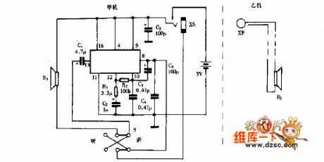
We can make a wired interphone easily by using a single chip IC TA7641 in AM radio.The interphone circuit is shown as follows.The interphone is formed by A and B.A is the host,and B is extension.Actually,B is a speaker B2.A and B is connected by twinax cable.When plug XP is inserted to socket XS,the interphone runs.Switch S is a talkback transfer switch.As the following picture,A is in speech state, and B is for obedient state.
(View)
View full Circuit Diagram | Comments | Reading(1530)
| Pages:100/126 At 2081828384858687888990919293949596979899100Under 20 |
Circuit Categories
power supply circuit
Amplifier Circuit
Basic Circuit
LED and Light Circuit
Sensor Circuit
Signal Processing
Electrical Equipment Circuit
Control Circuit
Remote Control Circuit
A/D-D/A Converter Circuit
Audio Circuit
Measuring and Test Circuit
Communication Circuit
Computer-Related Circuit
555 Circuit
Automotive Circuit
Repairing Circuit