
Index 83
REPEATER_BEEPER
Published:2009/6/23 1:38:00 Author:Jessie
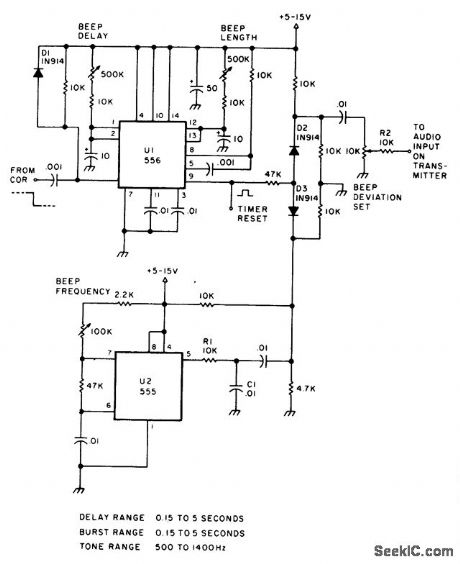
The signal from COR triggers U1 which produces a beep-gate pulse that enables the analog gate consisting of D2 and D3 to pass the beep tone generated by U2. (View)
View full Circuit Diagram | Comments | Reading(1010)
TELEVISION_VERTICAL_DEFLECTION_CIRCUIT
Published:2009/6/22 23:40:00 Author:May
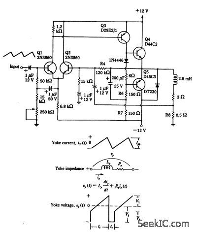
Two transistors are used to drive the yoke(2.5 mH + 0.3Ω) in this deflection circuit. R8 samples the yoke current and provides feedback to Q2, resulting in a very linear current ramp through the yoke. (View)
View full Circuit Diagram | Comments | Reading(0)
TELEVISION_VERTICAL_DEFLECTION_CIRCUIT
Published:2009/6/22 23:40:00 Author:Jessie
Two transistors are used to drive the yoke(2.5 mH + 0.3Ω) in this deflection circuit. R8 samples the yoke current and provides feedback to Q2, resulting in a very linear current ramp through the yoke. (View)
View full Circuit Diagram | Comments | Reading(1702)
TEMPERATURE_SENSOR
Published:2009/6/22 23:09:00 Author:Jessie
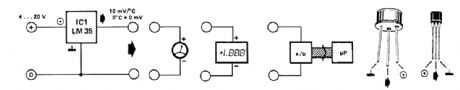
The LM35 temperature sensor provides an output of 10 mV/℃ for every degree Celsius over 0℃. At 20℃ the output voltage is 20 x 10 = 200 mV. The circuit consurnes 60 μA. The load resistance should not be less than 5 kΩ. A 4- to 20-V supply can be used. (View)
View full Circuit Diagram | Comments | Reading(2)
TELEPHONE_CIRCUIT
Published:2009/6/22 22:58:00 Author:May
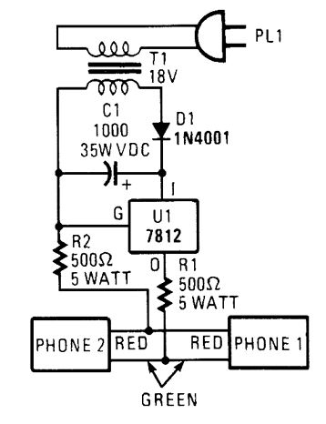
This circuit is useful for checking out old telephones by providing them with the dc voltage that they require for operation. (View)
View full Circuit Diagram | Comments | Reading(0)
KEY_WIRELESS_RTS_WITH_DATA
Published:2009/6/22 23:02:00 Author:Jessie
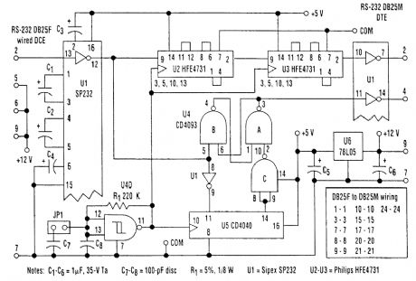
This simple keyer supplies both the RTS control and data delay needed to interface a digital ra-dio with an RS-232, data-only system. It supports speeds to 19.2 kbits/s sync or async. (View)
View full Circuit Diagram | Comments | Reading(1576)
THERMOMETER_FOR_5_V_OPERATION
Published:2009/6/22 23:02:00 Author:Jessie
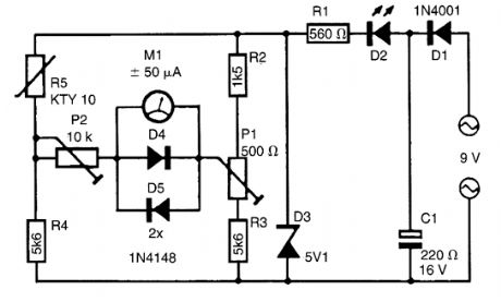
At the heart of this simple circuit is the well-known type KTY10 temperature sensor from Siemens. This silicon sensor is essentially a temp erature -dependent resistor that is connected as one arm in a bridge circuit here. Preset P1 functions to balance the bridge at 0℃. At that temperature, moving coil meter M1 should not deflect, i.e., the needle is in the center position. Temperature vari-ations cause the bridge to be unbalanced, and hence produce a proportional indication on the meter. Calibration at, say, 20℃ is carried out with the aid of P2.The bridge is fed from a stabilized 5.1-V supply, based on a temperature-compensated zener-diode. It is also possible to feed the thermometer from a 9-V battery, provided D1-D3, R1 and C1 are replaced with a Type 78L05 voltage regulator, because this is more economic as regards to current c onsumption. (View)
View full Circuit Diagram | Comments | Reading(2178)
PG_PASSWORD_PROTECTOR
Published:2009/6/22 23:01:00 Author:Jessie
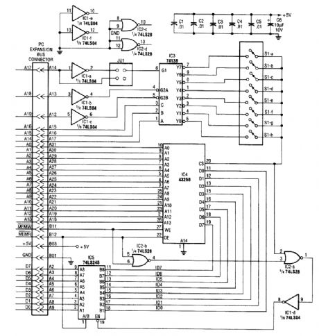
IC4, a static RAM, is mounted in a smart built-in switch over circuitry. This retains SRAM con-tents when power is off. The rest of the circuitry consists of address decoding logic and jumper JU1, used to decode a 16K address space for the 32K static RAM. Software is necessary and this is con-tained in the original article (see reference). (View)
View full Circuit Diagram | Comments | Reading(1900)
TEMPERATURE_COMPENSATION_ADJUSTER
Published:2009/6/22 23:01:00 Author:Jessie
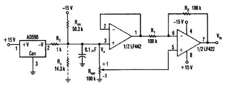
The circuit shown delivers +10 to -10 mV°/C output using an Analog Devices' AD590 temperature transducer. Rx is a scaling resistor. (View)
View full Circuit Diagram | Comments | Reading(1210)
TELEPHONE_LINE_TESTER
Published:2009/6/22 22:59:00 Author:Jessie
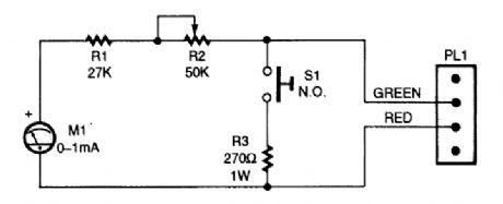
The telephone-line tester consists of nothing more than a meter (that's used to measure line voltage in the on- and off-hook state), three resistors (one of which is variable), a pushbutton switch, and a modular telephone connector. When the circuit is connected to the telephone line, a meter reading of 5 to 10 V (when S1 is pressed) indicates that the line is okay. (View)
View full Circuit Diagram | Comments | Reading(2604)
TELEPHONE_CIRCUIT
Published:2009/6/22 22:58:00 Author:Jessie
This circuit is useful for checking out old telephones by providing them with the dc voltage that they require for operation. (View)
View full Circuit Diagram | Comments | Reading(1693)
TELEPHONE_HOLD_CIRCUIT
Published:2009/6/22 22:57:00 Author:Jessie
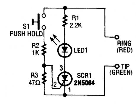
When S1 is pressed, the SCR fires, and places LED1 and R1 across the phone line. The line volt-age drops to about 20 V, which holds the connec-tion to the phone company's central office. (View)
View full Circuit Diagram | Comments | Reading(1597)
DARKNESS_MONITOR
Published:2009/6/22 22:45:00 Author:Jessie
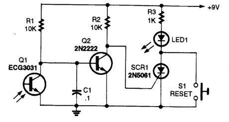
When light strikes detector Q1,Q2 is cut off,allowing bias to reach SCR1,triggering SCR1 and lighting LED1,S1 resets the circuit. (View)
View full Circuit Diagram | Comments | Reading(784)
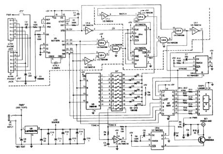
5_V_DIAL_TONE_CIRCUIT
Published:2009/6/22 22:45:00 Author:May
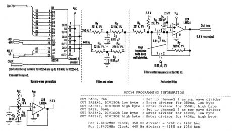
This circuit uses inexpensive, common components to generate a precise dial tone for phone applications (see the figure). U1 (an Intel 82C54 timer-counter) generates 350- and 440-Hz square waves that are filtered by R1/C1 and R3/C2, and mixed together by resistors R2 and R4.An operational amplifier configured as a 395-Hz, Sallen-Key, second-order bandpass filter (halfway between 350 and 440 Hz) removes unwanted signal harmonics. Almost any timer-counter can be used as the signal source, so long as it produces roughly square-wave outputs. (View)
View full Circuit Diagram | Comments | Reading(1785)
PHONE_PAGER
Published:2009/6/22 22:42:00 Author:May
This pager allows you to use your in-house phone wiring as a PA system. It uses two tone decoders to detect a particular touch-tone key. This key enables an audio amplifier. (View)
View full Circuit Diagram | Comments | Reading(2328)
TELEPHONE_SCRAMBLER
Published:2009/6/22 22:38:00 Author:May
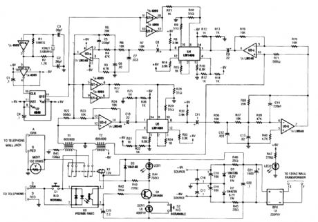
Two hybrids (T1 and T2) are used to allow direct connection to a telephone line. This circuit uses the common speech-in-version algorithm where the frequency of an audio signal is inverted about a center frequency. An LM1496 balanced modulator is used to heterodyne the specch range against a 3.58-kHz signal. (View)
View full Circuit Diagram | Comments | Reading(6)
SPEAKERPHONE_ADAPTER
Published:2009/6/22 22:29:00 Author:May
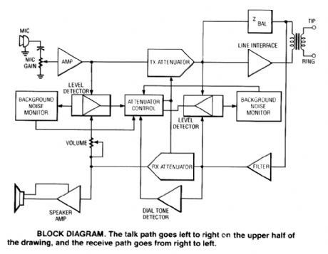
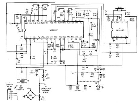
Using a Motorola MC34118 speakerphone IC, this adapter can be used with a regular telephone to provide speaker capability. This device is powered from the phone Iine, but it can be powered via an extemal power supply if the line loop current is marginally low. An external phone is needed for ringing and dialing functions. (View)
View full Circuit Diagram | Comments | Reading(4515)
PHONE_LINE_INTERFACE
Published:2009/6/22 22:26:00 Author:May
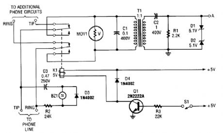
This circuit should be useful for interfacing phone projects to the telephone line. It has a ringer, can interrupt the wiring, and isolates project from the phone line. (View)
View full Circuit Diagram | Comments | Reading(2028)
SIMPLE_TELEPHONE_RING_INDICATORLINE
Published:2009/6/22 22:25:00 Author:May
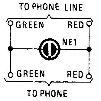
A neon lamp can easily be added to the phone line to act as a ring indicator. It's perfect for times when you can't hear the phone. (View)
View full Circuit Diagram | Comments | Reading(757)
TELEPHONE_BELL_SIMULATOR
Published:2009/6/22 22:24:00 Author:May

This circuit is intended for use in a small private telephone installation. The ringing tone se-quence is 400 ms on, 200 ms off, 400 ms on, 2 ms off. In the accompanying diagram, N1 and N2 form an oscillator that operates at a frequency of 5 Hz, which gives a period of 200 ms. The oscillator signal is fed to two decade sealers, which are connected in such a manner (by N3 and N4) that the in-put signal is divided by 15. The second input of N4 can be used to switch the divider on and off by logic levels. If this facility is not used, the two inputs of N4 should be interconnected. (View)
View full Circuit Diagram | Comments | Reading(773)
| Pages:83/126 At 2081828384858687888990919293949596979899100Under 20 |
Circuit Categories
power supply circuit
Amplifier Circuit
Basic Circuit
LED and Light Circuit
Sensor Circuit
Signal Processing
Electrical Equipment Circuit
Control Circuit
Remote Control Circuit
A/D-D/A Converter Circuit
Audio Circuit
Measuring and Test Circuit
Communication Circuit
Computer-Related Circuit
555 Circuit
Automotive Circuit
Repairing Circuit