
Index 87
Car Multi-Function Alarm Circuit
Published:2011/7/26 10:32:00 Author:Robert | Keyword: Car, Multi-Function, Alarm
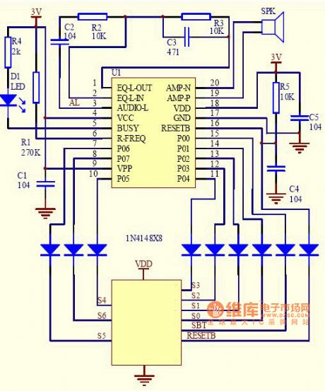
Functional requirements: When the car has got one of the malfunctions which could be detected by the system and the system would have the voice prompt alarm.Voices: left-front wheel; right-front wheel; left-rear wheel; right-rear wheel; right-rear wheel; too low tire pressure; too high tire pressure; please change battery; ding-dong.Control ways: parallel mode.voices' corresponding address: (it is added a 200ms mute case between every voice's combination)00H ding-dong + left-front wheel + too high tire prssure.01H ding-dong + right-front wheel + too high tire prssure.02H ding-dong + left-rear wheel + too high tire prssure.03H ding-dong + right-rear wheel + too high tire prssure.04H ding-dong + left-front wheel + too low tire prssure.05H ding-dong + right-front wheel + too low tire prssure.06H ding-dong + left-rear wheel + too low tire prssure.07H ding-dong + right-rear wheel + too low tire prssure.08H ding-dong + left-front wheel + please change battery.09H ding-dong + right-front wheel + please change battery.0AH ding-dong + left-rear wheel + please change battery.0BH ding-dong + right-rear wheel + please change battery.The circuit's principle diagram is shown in the pictrue. (View)
View full Circuit Diagram | Comments | Reading(947)
Contacting Two-Dimensional Tracking System Device Circuit
Published:2011/7/20 9:16:00 Author:Robert | Keyword: Contacting, Two-Dimensional, Tracking, System, Device
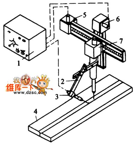
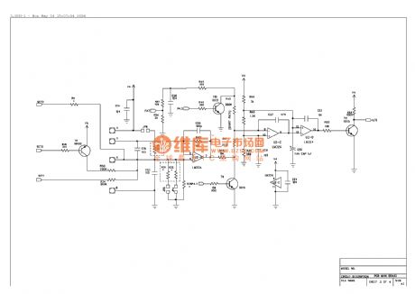
The picture shows the contacting two-dimensional tracking system device circuit.
The part 1 is control box. The part 2 is sensor bracket. The part 3 is the sensor. The part 4 is workpiece. The part 5 is horizontal adjustable sliding board. The part 6 is hight adjustable sliding board. The part 7 is welding head. (View)
View full Circuit Diagram | Comments | Reading(701)
Nokia 6110 circuit diagram 01
Published:2011/7/26 3:14:00 Author:Ecco | Keyword: Nokia
View full Circuit Diagram | Comments | Reading(945)
Nokia 6110 circuit diagram 02
Published:2011/7/26 3:14:00 Author:Ecco | Keyword: Nokia
View full Circuit Diagram | Comments | Reading(1019)
Scale cleaner
Published:2011/7/26 3:11:00 Author:Ecco | Keyword: Scale cleaner
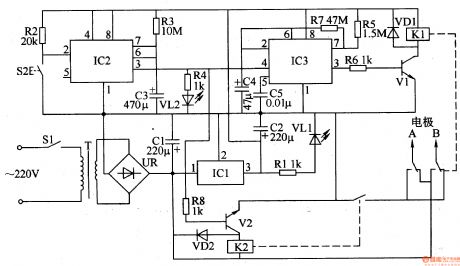
The scale cleaner circuit is composed of the power circuit, timer, multivibrator and control implementation circuit, and it is shown in Figure 3-211. Power supply circuit is composed of the power transformer T, bridge rectifier UR, filter capacitors Cl, C2, three-terminal integrated voltage regulator ICl, current limiting resistor Rl and power indicator LED VLl. The timer is composed of the time-base timer circuit IC IC2, start button S2, resistors R2, R3, capacitor C3, current limiting resistor R4 and LED VL2 and so on. Rl-R8 use the 1/4W or 1/8W carbon film resistors.
(View)
View full Circuit Diagram | Comments | Reading(622)
High-voltage Electrostatic Generator (the 2nd)
Published:2011/7/16 0:40:00 Author:Felicity | Keyword: High-voltage Electrostatic, Generator
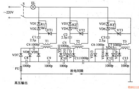
Work of the circuit
The circuit consists of oscillation step-up circuit and voltage doubler rectifier circuit. (It is showed in the picture 8-116.)
Oscillation step-up circuit consists of Resistors Rl-R3, capacitor Cl-C3, thyristor VTl-VT3, diode VDl-VD6 and step-up transformer Tl-T3.
Voltage doubler rectifier circuit consists of diode VD7-VDl6 and capacitors C4-Cl3.
When the high-voltage generator is working, sparks are produced in the discharge gap (gap is adjustable). This can limit the outputting voltage. It can also indicate whether the outputting voltage is zero or not. (View)
View full Circuit Diagram | Comments | Reading(2607)
Electronic mosquito killer
Published:2011/7/24 22:38:00 Author:Ecco | Keyword: Electronic mosquito killer
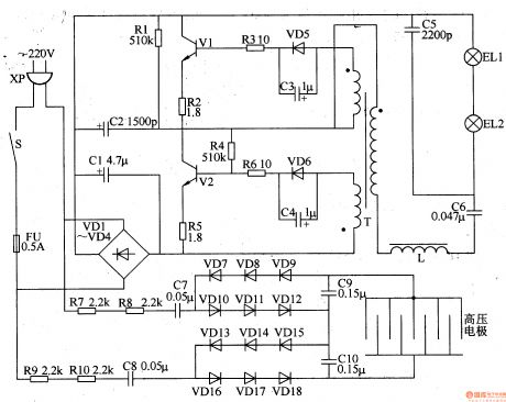
The electronic mosquito killer circuit is composed of the energy-saving lamp circuit and high-voltage generator circuit, and the circuit is shown in Figure 3-196. Energy saving lamp circuit is composed of the rectifier diodes VDl-VD6, transistors Vl, V2, resistors Rl-R6, capacitors Cl-C6, pulse transformer T, choke L and black fluorescents ELl, EL2. The high-voltage generator circuit consists of resistors R7-RlO, capacitors C7-ClO, rectifier diodes VD7-VDl8 and high electrodes. Rl-RlO choose the 1/4W carbon film resistors or metal film resistors. Cl uses aluminum electrolytic capacitor with the voltage in 400V.
(View)
View full Circuit Diagram | Comments | Reading(14325)
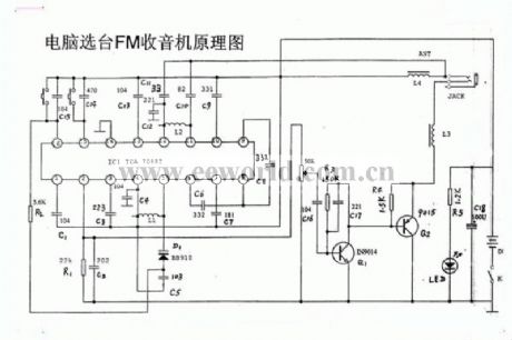
Auto-radio circuit diagram
Published:2011/7/22 1:29:00 Author:Ecco | Keyword: Auto-radio
View full Circuit Diagram | Comments | Reading(1565)
Drinking fountain circuit diagram 03
Published:2011/7/22 1:22:00 Author:Ecco | Keyword: Drinking fountain
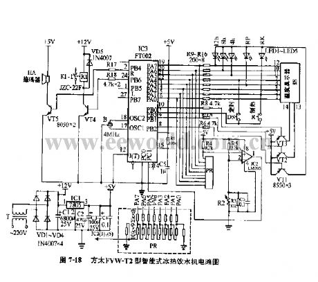
View full Circuit Diagram | Comments | Reading(939)
A cell phone charger
Published:2011/7/22 1:14:00 Author:Ecco | Keyword: cell phone charger
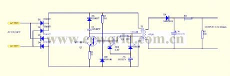
View full Circuit Diagram | Comments | Reading(696)
Drinking fountain circuit diagram 01
Published:2011/7/22 1:17:00 Author:Ecco | Keyword: Drinking fountain
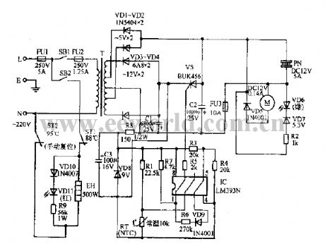
View full Circuit Diagram | Comments | Reading(1517)
Drinking fountain circuit diagram 02
Published:2011/7/22 1:24:00 Author:Ecco | Keyword: Drinking fountain
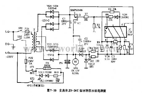
View full Circuit Diagram | Comments | Reading(1350)
Automatic Recording Telephone Interface Circuit
Published:2011/7/13 7:57:00 Author:Michel | Keyword: Telephone Interface Circuit
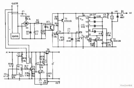
The automatic recording telephone interface circuit is shown as above.This circuit has the functions of automatic answer and recording.It needs install small tape recorder and solid recording chip.)The circuit is simple and it's needless to open the telephone when static current is less than 20μA.IC1 is a photoelectric coupler.IC2 is a decimal count/distributor and when the fourth ring ends,⑩ feet outputs high level,riggering behind circuit.IC3 is voice circuits which records The honest is absent,please leave a brief message. Primary B uses Φ0.1mm enameled wire to circle 350 turns,the secondary level adopts Φ0.07mm enameled wire to circle 1000 turns.
s (View)
View full Circuit Diagram | Comments | Reading(793)
Teana A33-EL power door lock circuit
Published:2011/7/16 2:56:00 Author:leo | Keyword: Power door lock
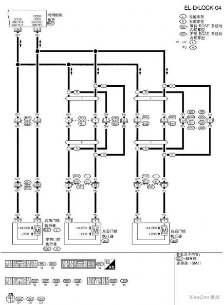
View full Circuit Diagram | Comments | Reading(593)
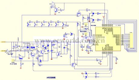
Xintai ZDP-78B computer-controlled horizontal electronic alexipharmic ark circuit diagram
Published:2011/5/13 1:03:00 Author:Ecco | Keyword: Xintai, computer-controlled , horizontal , electronic alexipharmic ark
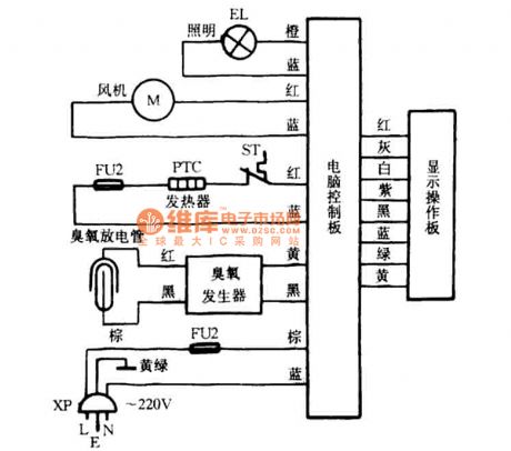
View full Circuit Diagram | Comments | Reading(623)
Half four-bit LCD digital display voltmeter circuit
Published:2011/5/13 2:56:00 Author:Nicole | Keyword: LCD, voltmeter
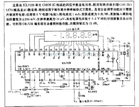
This half four-bit LCD digital display voltmeter is composed of ICL7129 single chip CMOS IC, and with a matrix multichannel scanning(100Hz) LCD digit display device, it is suitable for producing high resolution pocket multimeter. it has the function of automatic zero adjustment and do not need a external connected zero adjustment capacitor, it only needs 9V power supply, the power consumption is 1mA, the transpositional speed is 2/s, the measuring range of direct input analog voltage is ±200mV, the highest resolution is 10μV, it also has the functions of identifying alarm and displaying with lower than 7.2V power voltage. It can use OR/UR terminal to achieve range automatically transforming, the CMRR is 11dB. (View)
View full Circuit Diagram | Comments | Reading(2964)
Circuit diagram: fat analyzer circuit diagram _ page _3
Published:2011/6/30 21:49:00 Author:zj | Keyword: fat analyzer, page _3
View full Circuit Diagram | Comments | Reading(1260)
Circuit diagram: fat analyzer circuit diagram _ page _4
Published:2011/6/30 21:49:00 Author:zj | Keyword: fat analyzer, page _4
View full Circuit Diagram | Comments | Reading(675)
Rice cooker Circuit diagram 04
Published:2011/6/30 21:50:00 Author:zj | Keyword: Rice cooker
View full Circuit Diagram | Comments | Reading(1650)
Electric Water Heater Circuit 01
Published:2011/6/30 21:52:00 Author:zj | Keyword: Electric Water Heater, 01
View full Circuit Diagram | Comments | Reading(1277)
| Pages:87/126 At 2081828384858687888990919293949596979899100Under 20 |
Circuit Categories
power supply circuit
Amplifier Circuit
Basic Circuit
LED and Light Circuit
Sensor Circuit
Signal Processing
Electrical Equipment Circuit
Control Circuit
Remote Control Circuit
A/D-D/A Converter Circuit
Audio Circuit
Measuring and Test Circuit
Communication Circuit
Computer-Related Circuit
555 Circuit
Automotive Circuit
Repairing Circuit