
Index 95
X0640CE Field Scanning Output IC Internal Circuit
Published:2011/7/1 7:08:00 Author:Robert | Keyword: Field, Scanning, Output, IC, Internal
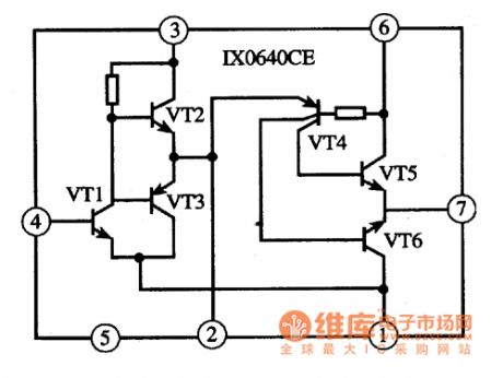
The 1X0640CE is a field scanning output IC produced by Japanese SHARP company which is widely used in many kinds of domestic and imported color TV sets.
The 1X0640CE IC has internal field excitation circuit, field output circuit, vertical blanking circuit and overheat protection circuit. Its internal circuit is shown in the picture.
The picture shows the 1X0640CE IC's internal circuit. (View)
View full Circuit Diagram | Comments | Reading(816)
DJ1001-063 Fan Single-Chip Micro-Computer Integrated Circuit
Published:2011/7/3 9:53:00 Author:Robert | Keyword: Fan, Single-Chip, Micro-Computer, Integrated

The DJ1001-063 is a fan single-chip micro-computer integrated circuit produced by Japanese NEC company which is widely used in many kinds of fan control circuits, such as the bats series.
1.Its functional features.
The DJ1001-063 IC has internal reset circuit, clock oscillation circuit, zero-crossing detecting circuit, LED display driving circuit, fan speed control circuit, key-bit scanning pulse generating circuit, key-bit command decoding circuit and other some auxiliary functional circuits.
2.Its pin's function and data
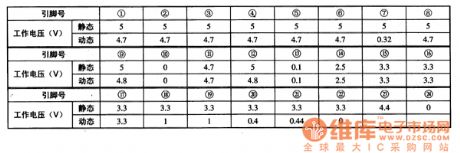
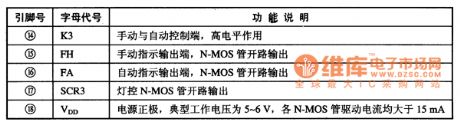
The DJ1001-063 IC uses 24-pin dual-row package and its pin's function is listed in table 1 and its working voltage is listed in table 2.
The table 1 shows the DJ1001-063 IC's pin's functions.
The table 2 shows the DJ1001-063 IC'w working voltage.
3.Typical application circuit
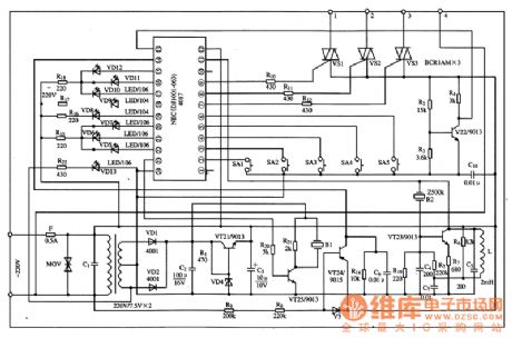
The fan control circuit typical application circuit composed of the DJ1001-063 IC is shown in picture 1.
The picture 1 shows the DJ1001-063 IC's typical application circuit. (View)
View full Circuit Diagram | Comments | Reading(767)
E0227 Range Hood Single-Chip Micro-Computer Integrated Circuit
Published:2011/7/3 9:20:00 Author:Robert | Keyword: Range Hood, Single-Chip, Micro-Computer, Integrated

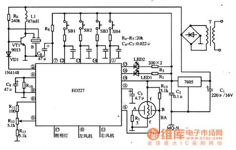
The E0227 is a range hood single-chip micro-computer IC which is used in many brands of range hoods.
1.Its functional features.
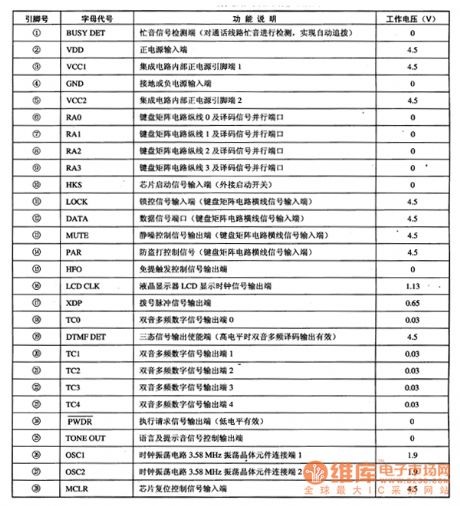
The E0227 IC uses 18-pin dual inline plastic package and its pin's functions are listed in table 1.
The table 1 shows the E0227 IC's pin's functions.
2.Typical application circuit.
The range hood control system typical application circuit composed of the E0227 IC is shown in the picture 1.
The picture 1 shows the range hood control system typical application circuit composed of E0227 IC. (View)
View full Circuit Diagram | Comments | Reading(833)
EB-03 Communication Single-Chip Micro-Computer Integrated Circuit
Published:2011/7/3 9:40:00 Author:Robert | Keyword: Communication, Single-Chip, Micro-Computer, Integrated
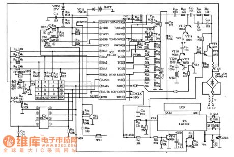
The EB-03 is a communication single-chip micro-computer IC which is widely used in Henghui series caller ID telephones.
1.Its functional features.
The EB-03 IC has internal clock oscillation circuit, key-bit pulse generating circuit, key-bit command coding circuit, dual-tone multi-frequency circuit, hands-free system caller ID control circuit, caller-inquiry circuit, hands-free trigger, serial data interface (providing displaying and storing data), mechanical lock and automatic recovering dialing circuit and other functional circuit.
2.Its pin's function and data
The EB-03 IC uses 28-pin dual-row package and its pin's function and data is listed in table 1.
The table 1 shows the EB-03 IC's pin's function and data.
3.Typical application circuit
The caller ID display control system typical application circuit composed of EB-03 IC is shown in picture 1.
The picture 1 shows the EB-03 IC's typical application circuit. (View)
View full Circuit Diagram | Comments | Reading(628)
Inductance Tuning Crystal Radio Circuit
Published:2011/6/28 6:08:00 Author:Michel | Keyword: Inductance Tuning Crystal Radio Circuit

First of all,the Q value of the spherical adjustable inductance coil is measured by Q table. the capacitor The capacitor of Q table is fixed on 55pf and the measuring result is:Maximum induction:550 KHz Q = 68,Middle induction:745 KHz Q = 60,Minimum induction:2770 KHz Q = 30.The capacitor of Q table is fixed on 80 pf and the measuring result is:Maximum induction:478 KHz Q = 77,Middle induction:995 KHz Q = 47,Minimum induction:2300 KHz Q = 15.
The coil's Q value is not high,especially the inside and outside coil reverse and the Q value is lower when the inductance cancel each other out.But it can used as crystal radio receiver tuning without variable capacitor and the line is simpler. (View)
View full Circuit Diagram | Comments | Reading(1540)
Module Super-regenerative FM Radio Cirucit of Electron Tube
Published:2011/6/22 5:00:00 Author:Michel | Keyword: Electron Tube, Module Super-regenerative, FM Radio Cirucit
Devices Selection
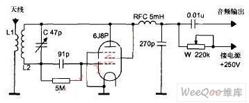
The machine circuit is shown in the picture and it is a superregenerative receiver circuit.Because most channel frequencies work between 88MHz~108MHz and take Shanghai literature and art channel (the middle frequency is 96.8MHz)as example.L2 uses Φ2mm silver-coated copper wire.On the diameter Φ15mm mould,it can be roped into 5 circles hollow type whose coil distance is 2mm. The distances between two circles is about 2mm-3mm.The radio frequency choke uses Φ0.32mm lacquered wire.The diameter 10mm paper tube is raped into 150 circles which is divided into three sections hives and the distance is 2mm. (View)
View full Circuit Diagram | Comments | Reading(7577)
Channel Selection and FM Circuit of TDA70887 Computer
Published:2011/6/28 6:12:00 Author:Michel | Keyword: TDA70887 Computer, Channel Selection, FM, Circuit
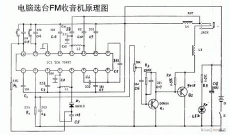
Channel Selection and FM Circuit of TDA70887 Computer (View)
View full Circuit Diagram | Comments | Reading(1776)
telecommunication equipment power measurement circuit
Published:2011/6/23 9:52:00 Author:Nancy | Keyword: telecommunication equipment, power measurement
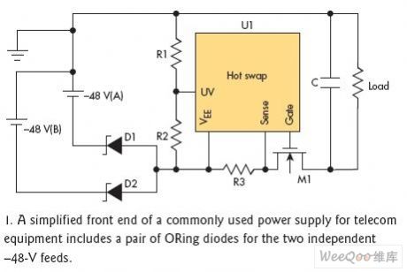

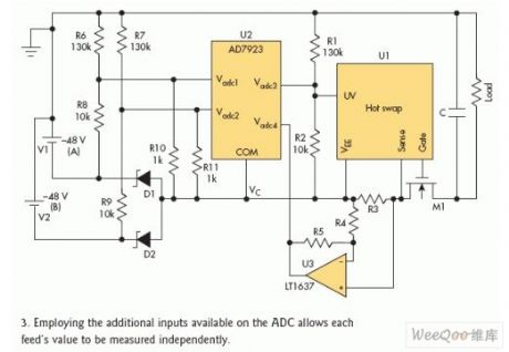
This article discusses how to measure the input voltage and current of telecommunication equipment which adopts two independent inputs (-48V(A) and -48V(B)). Each independent input voltage range is not norrow than -42.5V~-56.5V, and OR operation is used on the module for this two independent inputs with the consideration of redundance.From the point of maintenance and support, it is very important to measuring the input voltage, the power of the module and wether the input exsits.
Figure 1 is the simplified front end of the common power supply part of the telecommunication equipment. The OR operation of the two inputs is made by D1 and D2. Once the voltage through OR operation is higher than low-voltage threshold determined by R1 and R2, hot plug circuit (U1) add the electricity gradually for the load (data processing).
(View)
View full Circuit Diagram | Comments | Reading(1277)
Rural wire broadcasting disconnecting teller circuit diagram
Published:2011/6/13 4:57:00 Author:Lucas | Keyword: Rural, wire broadcasting, disconnecting teller
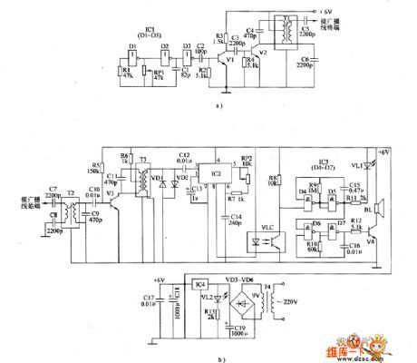
The rural wire broadcasting disconnecting teller circuit is composed of the carrier launched circuit, carrier receiving circuit, alarm circuit and power supply circuit, and the circuit is shown as the chart. Carrier launched circuit (cable radio lines are installed in the terminal) is composed of the high-frequency oscillator circuit and amplified output circuit. High-frequency oscillator consists of the NOT gates D1, D2 which are inside of NOT gate integrated circuit IC1 (D1 ~ D3), resistor R1, potentiometer RP1 and capacitor C1; Amplified output circuit is composed of the D3 which is inside of IC1, capacitors C2 ~ C6 , transistors V1, V2, resistors R2, R3 and IF transformer T1. R1 ~ R13 use 1/4W metal film resistors or carbon film resistors. RP1 and RP2 use small synthetic membrane potentiometer or variable resistor.
(View)
View full Circuit Diagram | Comments | Reading(681)
Seedling tent seedling growth stimulator circuit diagram
Published:2011/6/14 3:19:00 Author:Lucas | Keyword: Seedling tent, seedling growth stimulator
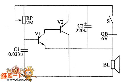
The seedling tent seedling growth stimulator circuit is composed of the transistors V1, V2, potentiometer RP, capacitors C1, C2, speaker BL, power switch S and battery CB, and the circuit is shown as the chart. V1, V2, and RP, C1 form a simple pulse generator. RP selects a small organic solid potentiometer or variable resistor. C1 chooses the monolithic capacitor or polyester capacitor; C2 selects the aluminium electrolytic capacitor with the voltage in 10V. V1 chooses 3DG6 or 59013 NPN silicon transistor; V2 uses 3AX31, 3AX81 or 3AX83 germanium PNP transistor. BL uses the 0.25W, 8Ω electric speaker. GB selects the 6V small-capacity maintenance-free battery. S uses the monopole tumble switch.
(View)
View full Circuit Diagram | Comments | Reading(1028)
optically controlled timing street light circuit
Published:2011/6/22 9:44:00 Author:Nancy | Keyword: optically controlled, timing street light
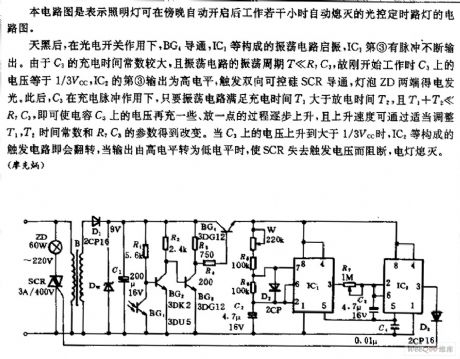
The circuit shown is a optically controlled timing street light circuit which indicates that the illuminating lamp can work automatically several hours at dusk and then automatically extinguish.
After dark, the BG4 conducts under the optoelectronic switch, the oscillator circuit formed by IC turns on, the ③ of IC1 outputs pulse continuously. For the charging time constant is large with the oscillating period of the oscillator circuit T ≤R7C3, the voltage of C3 is 1/3VCC at the beginning of operation, the ③ output of IC2 is high level, triggering SCR to conduct, both ends of lamp ZD energize and glow. (View)
View full Circuit Diagram | Comments | Reading(657)
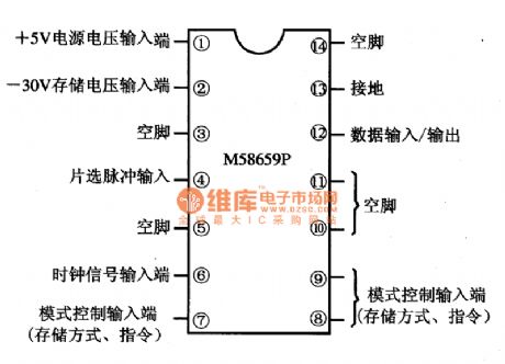
M58659P Memory Integrated Circuit
Published:2011/6/28 7:28:00 Author:Robert | Keyword: Memory, Integrated
The M58659P is a memory IC produced by the Japanese Mitsubishi company which is widely used in TV sets, audio equipments, air conditioners, computers and other control systems.
1.Its functional features.
The M58659P IC has internal digital input/output interface circuit, memory matrix circuit and data registers circuit and so on.
2.Its pin's functions and data.
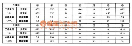
The M58659P IC uses 14-pin dual-in-line package. Its pin's functions are shown in the picture 8-36. Its working parameters are listed in table 8-35.
The picture shows the M58659P IC's pinout and pin's functions.
The table shows the M58659P IC's working parameter. (View)
View full Circuit Diagram | Comments | Reading(835)
M58658P Memory Integrated Circuit
Published:2011/6/28 7:34:00 Author:Robert | Keyword: Memory, Integrated
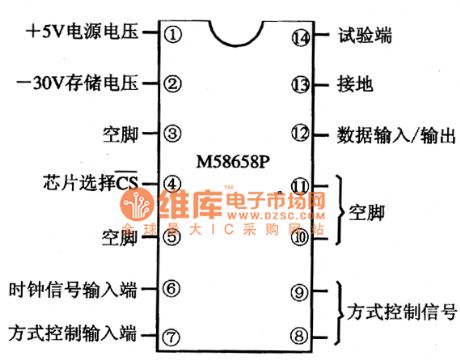
The M58658P is a memory IC produced by the Japanese Mitsubishi company which is widely used in TV sets, air conditioners,remote-control fansand other cases which needto store information.
1.Its functional features.
The M58658P IC has internal memory matrix circuit, digital input/output interface circuit, and registers circuit and so on.
2.Its pin's functions and data.
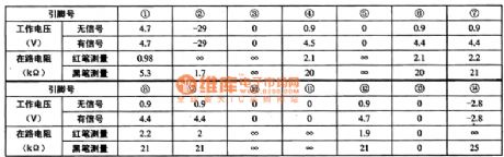
The M58658P IC uses 14-pin dual-in-line package. Its pin's functions are shown in the picture andits working parameters are listed in the table.
The picture shows the M58658P IC's pin's functions.
The table shows the M58658P IC's working parameter. (View)
View full Circuit Diagram | Comments | Reading(768)
M58655P Memory Integrated Circuit
Published:2011/6/28 7:43:00 Author:Robert | Keyword: Memory, Integrated
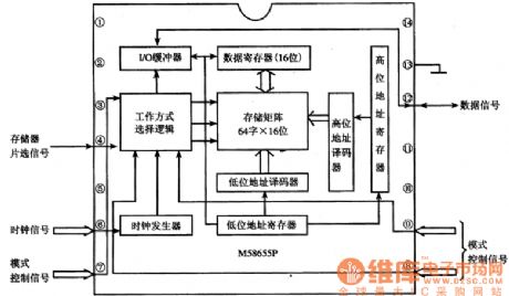
The M58655P is a memory IC produced by the Japanese Mitsubishi company which is widely used in TV sets, audio equipments, air conditioners and other control systems.
1.Its functional features.
The M58655P IC has internal UO buffer, data registers, memory matrix, working mode selection logic circuit, clock generater and registers, address decoding circuit and other some secondary function circuit. Its internal circuit diagram is shown in the picture.
The picture shows the M58655P IC's internal circuit diagram.
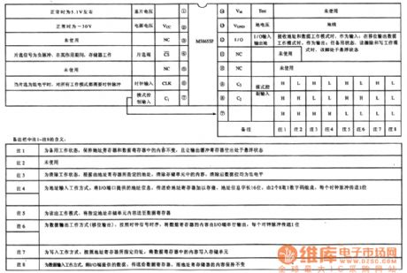
2.Its pin's functions and data.
The M58655P IC's pin's functions is shown in the picture and its working parameters is listed in the table.
The picture shows the M58655P IC's pin's functions.
The table shows the M58655 IC's working parameters. (View)
View full Circuit Diagram | Comments | Reading(1084)
M58653P Memory Integrated Circuit
Published:2011/6/28 7:52:00 Author:Robert | Keyword: Memory, Integrated
The M58653P is a memory IC produced by the Japanese Mitsubishi company which is widely used in many brands of color TV sets.
1.Its functional features.
The M58653P IC has internal data input/output interface circuit, memory matrix circuit, mode control circuit and so on.
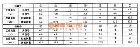
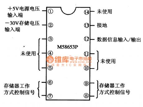
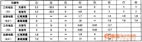
2.Its pin's functions and data.
The M58653P IC uses 14-pin dual-in-line plastic structure. Its pin's functions are shown in the picture and its working parameters are listed in the table.
The picture shows the M58653P IC's pin's functions.
The table shows the M58653P IC's main pin's working parameters. (View)
View full Circuit Diagram | Comments | Reading(650)
KY101 IC Typical Application Circuit
Published:2011/6/28 7:57:00 Author:Robert | Keyword: IC, Typical, Application
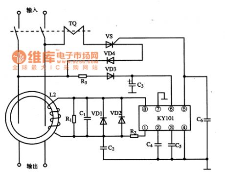
The KY101 is a special IC for earth leakage protection which is widely used in many kinds of leakage protectors.
The earth leakage protector's typical application circuit composed of KY101 IC is shown in the picture. This circuit's static working current is about 2mA.
The picture shows the KY101 IC's typical application circuit. (View)
View full Circuit Diagram | Comments | Reading(984)
KS57C2616QFP IC Typical Application Circuit (1)
Published:2011/6/22 7:53:00 Author:Robert | Keyword: IC, Typical, Application
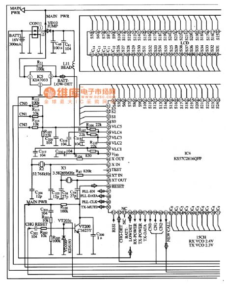
The KS57C2616QFP is a communication single-chip micro-computer IC which is mainly used as the mobile phone control microprocessor in the cordless telephone.
The KS57C2616QFP IC's internal part is made upof CPU, keys scanning pulse generating circuit, keys command coding circuit, clock oscillation circuit (main oscillation and displaying oscillation), charging detecting circuit, power control circuit, PLL circuit, screen displaying decoding driving circuit and so on.
The KS57C2616QFP IC uses 100-pin quatuor package and its typical application circuit is shown in the pictrue.
The picture shows the KS57C2616QFP IC's typical application circuit. (View)
View full Circuit Diagram | Comments | Reading(521)
CW9561 Analog Sound Integrated Circuit
Published:2011/6/23 6:18:00 Author:Robert | Keyword: Analog, Sound, Integrated

The CW9561 analog sound integrated circuit is a IC which can play the alarm sound, whistle sound, police cars sound and guns sound. Its typical application circuit is shown in the picture. In the circuit shown in picture (a), when the switch S2 is set separately at the position of A, B and C, this circuit would play the alarm sound, whistle sound and police cars sound. When the switch S1 is closed, the circuit would play the guns sound no matter which position the switch S2 is set. In the circuit shown in picture (b), the switch S2 is a double-pole four-throw switch. When it is set to one of the stages, the circuit would separately play the alarm sound, guns sound, ambulances sound and fire-fighting vehicle sound. (View)
View full Circuit Diagram | Comments | Reading(757)
KA3524 IC Typical Application Circuit
Published:2011/6/25 21:13:00 Author:Robert | Keyword: IC, Typical, Application
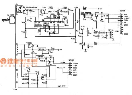
The KA3524 is a PWM switching power IC produced by the Samsung company which has many applications in the players, air conditioner control systems, computers and monitors.
The switching power typical application circuit composed of KA3524 IC is shown in the picture.
The picture shows the KA3524 IC's typical application circuit. (View)
View full Circuit Diagram | Comments | Reading(2142)
KA2410 IC Typical Application Circuit
Published:2011/6/27 8:58:00 Author:Robert | Keyword: IC, Typical, Application
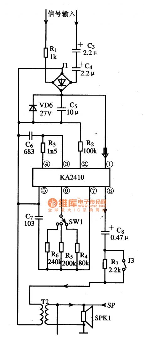
The KA2410 is a ringer IC produced by the Korean Samsung company which is widely used in communication equipments. It is mainly used for ringer.
The ringer circuit typical application circuit composed of KA2410 IC is shown in picture.
The picture shows the KA2410 IC's typical application circuit. (View)
View full Circuit Diagram | Comments | Reading(1788)
| Pages:95/126 At 2081828384858687888990919293949596979899100Under 20 |
Circuit Categories
power supply circuit
Amplifier Circuit
Basic Circuit
LED and Light Circuit
Sensor Circuit
Signal Processing
Electrical Equipment Circuit
Control Circuit
Remote Control Circuit
A/D-D/A Converter Circuit
Audio Circuit
Measuring and Test Circuit
Communication Circuit
Computer-Related Circuit
555 Circuit
Automotive Circuit
Repairing Circuit